Site pages
Current course
Participants
General
MODULE 1.
MODULE 2.
MODULE 3.
MODULE 4.
MODULE 5.
MODULE 6.
MODULE 7.
MODULE 8.
MODULE 9.
MODULE 10.
MODULE 11.
MODULE 12.
MODULE 13.
MODULE 14.
MODULE 15.
MODULE 16.
MODULE 17.
MODULE 18.
MODULE 19.
LESSON 7. Filter- classification-components-Inductor, capacitor. Filter-LC, π filter-Active low pass and high pass filter.
Filters:
A filter is a circuit or device that allows some frequencies to pass through and attenuates other frequencies.
Based on the construction, filters can be classified as (i)Passive filters and (ii) Active filters.
Passive filters – Filters that use only passive elements such as resistors, capacitors and inductors are called Passive filters.
Active filters – Filters that use active devices such as transistors or op-amps are called Active filters.
The performance of active filters is better than passive filters. Further, low cost integrated op-amps have helped to make active filters popular. They have an advantage at lower frequencies.
Resistors:
Physical materials resist the flow of electrical current to some extent. Certain materials such as copper offers very low resistance to current flow, and hence they are called as conductors. Other materials such as ceramic which offer extremely high resistance to current flow are called as insulators. In electric and electronic circuits, there is a need for materials with specific values of resistance in the range between that of a conductor and insulator. These materials are called as resistors and their value of resistance are expressed in ohms.
Types of resistors:
-
Fixed resistors – Carbon composition, carbon film, metal film, wire wound etc
-
Variable resistors – Potentiometer, Rheostat, Trimmer
Capacitors:
Capacitors are the devices which can store electric charge. The energy stored in the capacitor is given by,

Where, C – Capacitance, Farad
V – Voltage across the capacitor
A capacitor consists of two conductive plates separated by a dielectric material.
Inductors:
Inductors store energy in the form of magnetic field and deliver it as and when required. Whenever current passes through a conductor, lines of magnetic flux are generated around it. This magnetic flux opposes any change in current due to the induced emf. This opposition to the change in current is known as inductance and the component producing inductance is known as inductor. The unit of inductance is Henry (H). The inducexd emf is given by,

where, e – induced emf in volts
L – Inductance in Henry
di/dt – rate of change of current
Filters:
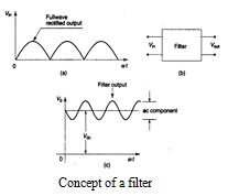 The output of a rectifier contains dc component as well as ac component. Filters are used to minimize the undesirable ac ie., ripple leaving only the dc component to appear at the output ie., Filters are used to remove the ripple from the d.c output. The commonly used filters are listed below:
-
Inductor filter
-
Capacitor filter
-
LC filter
-
π - filter
Inductor filter
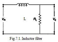 In consists of a choke in series with the load as shown in the Figure 7.1. The Inductor has the inherent characteristic of opposing any change in the current. Hence the introduction of choke in the rectifier circuit will have a smoothing effect. The inductive filter is suitable for heavy loads.
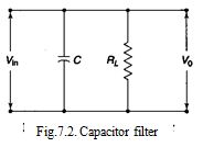
Capacitor filter
 In consists of a choke in series with the load as shown in the Figure 7.1. The Inductor has the inherent characteristic of opposing any change in the current. Hence the introduction of choke in the rectifier circuit will have a smoothing effect. The inductive filter is suitable for heavy loads.
It consists of a capacitor directly across the load as shown in the Figure7.2. At light loads, the capacitor filter maintains the output voltage near to maximum voltage (Vm). The capacitor charges up to the maximum value of input voltage and maintains the value even as the fullwave voltage drops to zero.
The discharge of capacitor through load resistance takes place till the input voltage raises to a value more than the capacitor voltage. Thus the diode will again be forward biased causing recharging of capacitor due to diode current. However, as the load increases, the ripple also increases due to the greater discharge of the capacitor.
LC filter
We have seen that, in the case of L-filter the ripple increases with decrease in the load, where as the ripple increases with increases in load in the C-filter. Hence the combination of these two filters namely, LC filter has to make the ripple independent of the load. The LC filter circuit is shown in Figure 7.3. 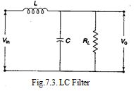
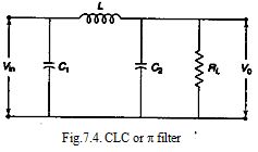
CLC or p-Filter
The use of CLC or p-filter improves the filtering process. The circuit arrangement is as shown in the Figure 7.4. In some cases, for light loads, the inductor may be replaced by a resistor.
Active low pass filter
A filter circuit allows only a certain range of frequencies to pass freely (without attenuation) while suppressing other frequencies. Filter circuits are classified as low pass, (i.e., low frequencies from 0 to a certain cut off frequency fc allowed to pass), high pass, (ie., frequencies above a cut off frequency fc are allowed to pass), band pass, (i.e frequencies within a specified band are allowed to pass ) and band stop, (i.e. frequencies within a specified band are suppressed). Filter circuits can be fabricated from passive components, i.e., resistors, capacitors and inductors. An active filter uses an operational amplifiers are very suitable due to good characteristics of operational amplifiers.
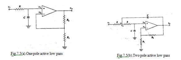
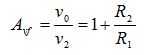
Figure 7.5(a) shows a one pole active low pass filter and figure 7.5(b) shows a two pole active low pass filter. The closed loop gain Avf from inverting input to the output is,
The cut off frequency fc of the by-pass circuit consisting of R and C is

When Avf = 1.586 the cut off frequency fc is given by the equation. At cut off frequency the overall gain is down 3 dB. Above fc the voltage gain decreases 40 dB per decade increase in frequency.
Active high pass filter
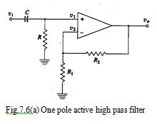
Figure 7.6(a) shows a one pole high pass filter and figure 6.6(b) shows a two pole high pass filter. It uses acoupling circuit consisting of R and C. It passes high frequencies but blocks the low frequencies. The closed loop gain Avf from inverting input to output is
The cut off frequency fc of the by-pass circuit consisting of R and C is
![]()
Last modified: Wednesday, 4 December 2013, 10:57 AM