Site pages
Current course
Participants
General
Module- 1 Scope and importance of food processing....
Module- 2 Processing of farm crops; cereals, pulse...
Module- 3 Processing of animal products
Module- 4 Principal of size reduction, grain shape...
Module- 5 Theory of mixing, types of mixtures for ...
Module- 6 Theory of separation, size and un sized ...
Module- 7 Theory of filtration, study of different...
Module- 8 Scope & importance of material handl...
19 April - 25 April
26 April - 2 May
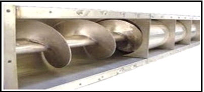
Lesson 32 Screw Conveyor
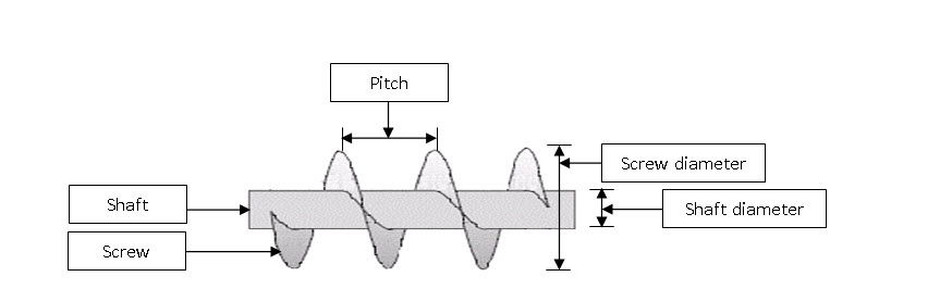
The screw conveyor consists of a tubular or U-shaped trough in which a shaft with spiral screw revolves. The screw shaft is supported by end and hanger bearing. The rotation of screw pushes the grain along the trough. The screw conveyor is used in grain handling facilities, animal feed industries and other installations for conveying of products generally for short distances. Screw conveyor requires relatively high power and is more susceptible to wear than other types of conveyors. The pitch of a standard screw which is the distance from the centre of one thread to the centre of the next thread, is equal to its diameter.
The screw conveyor’s driving mechanism is simpler and no tensioning device is required therefore, the initial cost of the conveyor is lower than any other conveyor with the same length and capacity. The main parts of a screw conveyor are, screw blade, screw shaft, trough, inlet and outlet gates, bearings and drive mechanism.
The screw conveyor is generally used to move grains horizontally. However, it can also be used at any angle upto 90° from the horizontal, but the capacity correspondingly reduced as per the inclination of conveyance.
The screw basically consists of a shaft and the screw blade or flight. The flight is a continuous one piece helix, shaped from a flat strip of steel welded onto the shaft. The serew shaft is usually a jointless tube with thick sides and a high tensile shtrength to reduce the weight. The thickness of the steel strip helix decreases from the innter edge to the outer edge.
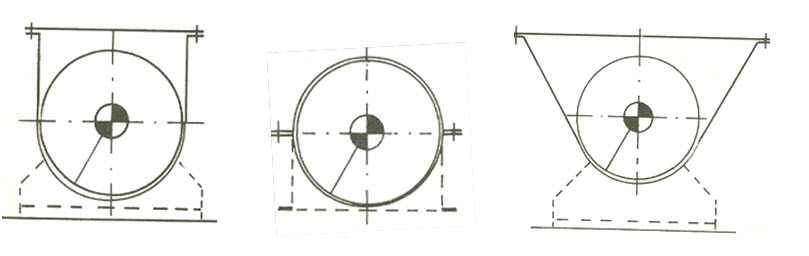
Troughs of screw conveyor have different shapes. Most commom is U-shaped trough. In an enlarged or flared trough the side walls become wider at the top. This type of trough is usually used for conveying non-easy flowing materials which may have lumps. The tubular trough is completely closed with circular x-section and mostly used for conveying materials at inclination or for vertical lift.
For operational reasons, some gap is provided between the edge of the screw blade and the trough walls. Due to this gap, it is not possible to completely empty the trough of a horizontal screw conveyor. If the screw conveyor is used to convey different materials, mixing of products is possible. Also, when the kernels are pressed between the serew edge and trough walls, they can be damaged. During conveyance, the kernels are also subjected to continuous friction with the trough walls. Screw conveyor may be designed for clockwise or counter-clockwise rotation. The change in direction of roatation does not affect the capacity.
The capacity of screw conveyor is influenced by the screw diameter, inclination of the screw blade, speed of the blade, shaft diameter and cross-section of loading. The theoretical conveyance capacity of the screw conveyor can be calculated by the following equation.
Capacity , ![]()
Where,
D = screw diamter, m
d = shaft diameter, m
p = pitch, m
n = rpm
The power requirement of screw conveyors for horizontal operation may be deternimined by the following equation.

Where,
Q = conveyor capacity, 
L = conveyor length, m
W = bulk material weight, ![]()
F = material factor
Screw conveyors can be operated in an inclined position. In this case, the material will be conveyed upward. The capacity of inclined screw conveyor decreases than the horizontal operation. Loading and discharge of a screw conveyor can be take place at sevaral places.
The product supply should be regular to avoid overfilling and congestion in a screw cpnveyor. To regularize product flow an adjustable opening at the feeding point should be provided. The product can be discharged either at the end of the screw or the intermediate discharge can be achieved through an opening in the bottom of the trough.
Pneumatc Conveyor
The pneumatic conveyor moves granular materials in a closed duct by a high velocity air stream. Pneumatic conveying is a continuous and flexible transportation method. The material is carried in pipelines either by suctuion or blowing pressure stream. The granular materials because of high air pressure are convayed in dispersed condition. For dispersion of bulk material, air velocities in the range of 15 – 30 m/s is necessary.
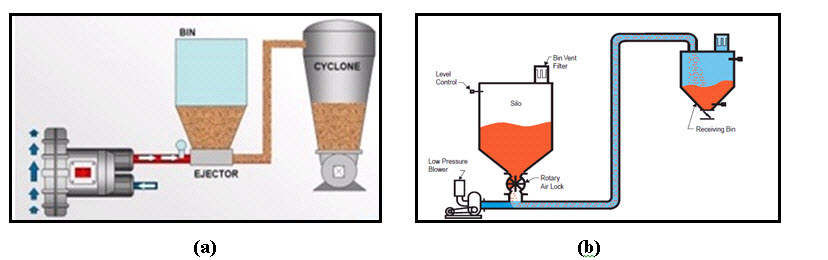
The pneumatic conveying system needs a source of air blowing or suction, means of feeding the product into the conveyor, ducts and a cyclone or receiving hopper for collection of product. There are three basic systems of pneumatic conveying. These are pressure or blowing system, suction or vacuum system and combined push-pull or suck blow system.
In blowing or positive pressure systems, the product is conveyed by using air pressures greater than the atmospheric pressure. The selection of air mover is the most important aspect of the design of a pneumatic conveying system. Two factors, supply air pressure and the volumetric flow rate of air should be considered in designing.
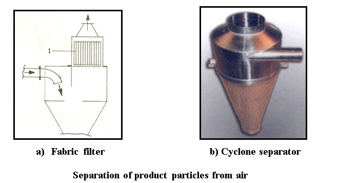
For separation of product particles from air, air-product separators are used. Cyclones are mostly used to collect the particles. Cyclone is a device which removes the bulk of the product particle from the conveying air stream by centrifugal force. In some cyclone, a fabric filter is attached to remove residual dust and fine product particles from the air stream.
The volumetric flow rate of air depends on the necessary air velocity and pipe or duct size used in the system. In pneumatic conveying systems, fans and blowers with high voulmetric flow rates and lowe pressures to positive displacement compressors producing high pressures are used.
Last modified: Saturday, 5 October 2013, 10:36 AM