Site pages
Current course
Participants
General
MODULE 1. Magnetism
MODULE 2. Particle Physics
MODULE 3. Modern Physics
MODULE 4. Semicoductor Physics
MODULE 5. Superconductivty
MODULE 6. Optics
5 April - 11 April
12 April - 18 April
19 April - 25 April
26 April - 2 May
LESSON 28. Introduction to Optical Fiber System
Fiber Optic Communication System
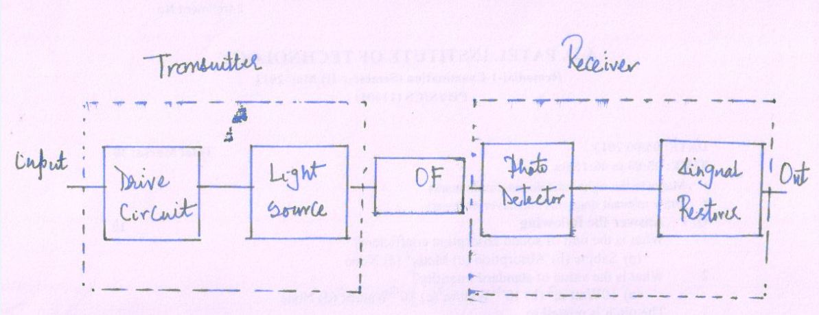
A Fiber Optic Communication System has three major components;
Transmitter:
-
It consists of a light source supported by suitable drive circuit.
-
It converts electrical signal to light signals with the help of transducer.
-
Transducer converts a non-electrical message into an electrical signal and is fed to a light source.
-
Light source is very small either LED or LASER
-
Here, light waves are modulated with the electrical signals; the change in the intensity of LED or LASER beam gives analog modulation.
-
Such analog modulation is converted into digital (present of light pulse indicates as 1 and absence of light pulse indicates as 0) modulation by flashing of light source. A massage can be transmitted by number 1s or 0s.
-
Optical Fiber: transmit the signal
The optical signal travelling through the fiber will get weaker (attenuated) and twist out of shape (distorted) due to spreading over wide area (dispersion).
Output light from the fiber directs to the semiconductor photodiode, which converts the light signals to electrical signals
Receiver:
-
It captures the signals (light signals) at the other end of the fiber and converts them to electrical signals.
-
The electrical signals are amplified
-
Receiver is programmed to accept such digital signals. It can re-construct the original massage.
Physical Structure
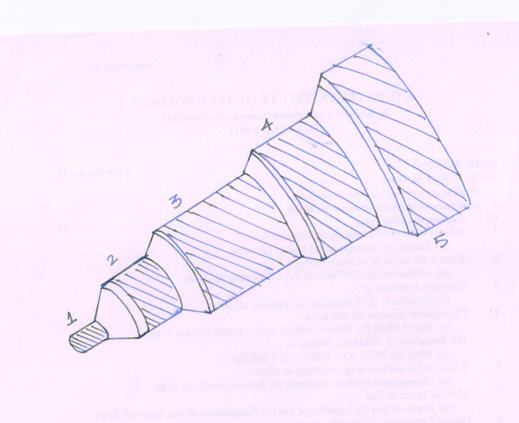
Fig19(2)
Core
-
It is inner light carrying member.
-
The innermost cylindrical region is the light guiding region.
-
The diameter of the core is of the order of 8.5 \[\mu m\] to 62.5 \[\mu m\]
-
Refractive index of the core is n1.
Cladding
-
It is middle layer, which serves to confine the light to the core.
-
It is surrounded by a coaxial middle region.
-
The diameter of the cladding is of the order of 125 \[\mu m\] -200 \[\mu m\]
-
Refractive index of cladding is n2
-
Refractive index of cladding (n2) is always greater than Refractive index of the core (n1).
Buffer Jacket
-
The outermost region is called the sheath or protective buffer coating.
-
It is plastic coating given to the cladding for extra protection.
-
This coating is applied during the manufacturing process.
-
It surrounds the cladding, which protects the fiber from physical damage and environment effect.
-
The buffer coating can vary in size from 250 \[\mu m\] -900 \[\mu m\]
-
It avoids fiber leakage excessive optical attenuation.
Kevlar
-
It is yarn type of material.
-
It is strength member that provides toughness and tensile strength of the cable.
Polyurethane
-
Outermost jacket covers all inner layers and provides flexibility, ruggedness and avoid moisture to come in contact with the fiber.
Basic Principle
Transmission of light through an optical fiber is based on the phenomenon of Total Internal Reflection (TIR). TIR obeys the laws of reflection.
Let a medium having a lower refractive index (n2) is said to be an optically rarer medium and a medium having a higher refractive index (n1) is said to be an optically denser medium.
When a beam of light travels from a denser (n1) to rarer medium (n2).
The incident ray makes angle with normal in the denser medium is called the angle of incident. Some rays are partially internally reflected in the same medium.
The ray is transmitted (refracted) in the rarer medium. It is bent away from the normal in the rarer medium and makes the angle with respect to the normal known as refracted angle.
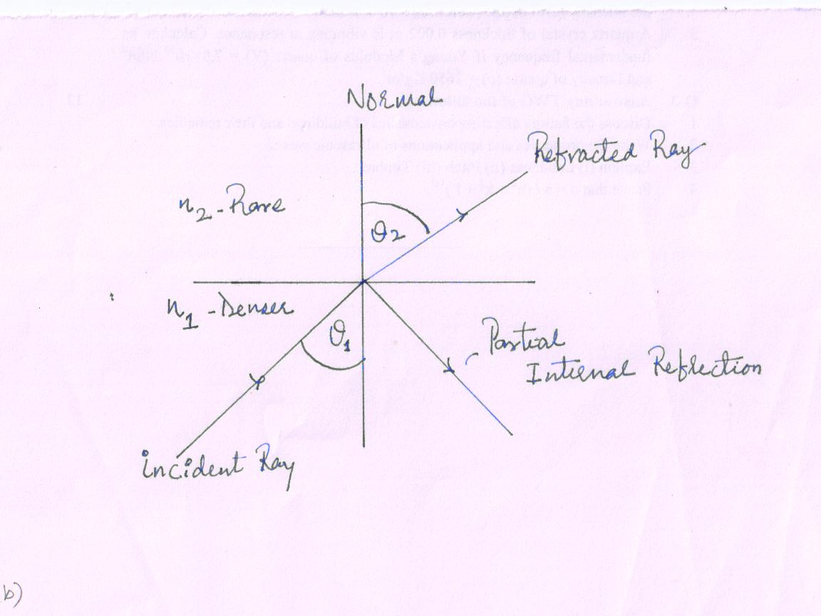
Fig 19(3a).
Here, beam of light changes the medium; however we can apply the Snell’s Law
\[{{\sin {\theta _1}} \over {\sin {\theta _2}}}\] = \[{{{n_2}} \over {{n_1}}}\]
Where,
θ1 - Angle of incident in denser medium
θ2 - Angle of refraction in rarer medium
n1 - Refractive index of denser medium (n1 > n2 )
n2 - Refractive index of rarer medium
Now, the angle on incident (θ1) in the denser medium is increased, the refracted angle (θ2) increases and the transmitted rays bend more and more away from the normal. However, at some particular position of the angle of incident in denser medium, the refracted ray glides along the boundary surface so that the refracted angle becomes 90° with respect to the normal
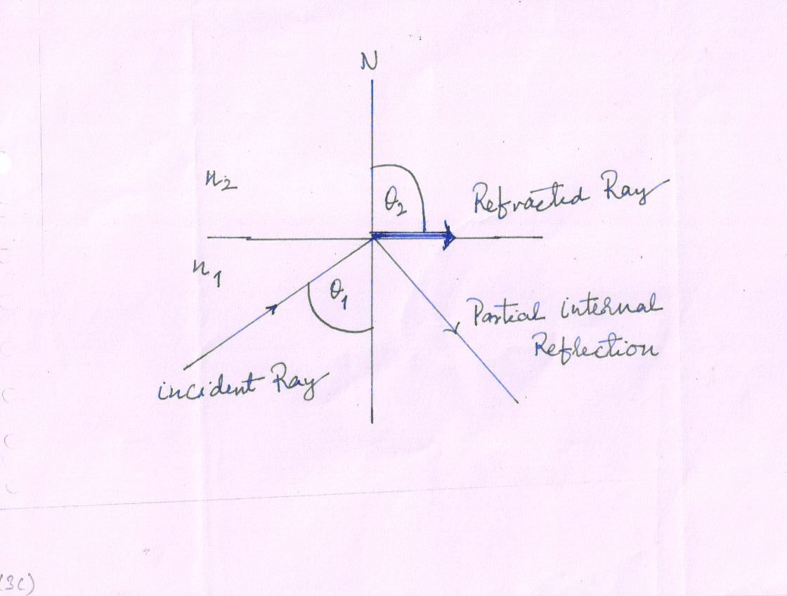
Fig 19(3b).
The particular position of the angle of incident (θ1) in denser medium is called critical angle (θc ). Again we can apply the Snell’s Law
\[{{\sin {\theta _1}} \over {\sin {\theta _2}}}\] = \[{{{n_2}} \over {{n_1}}}\]
If, θ2 = 90º at that time θ1 = θc = critical angle
\[{{\sin {\theta _c}} \over {\sin 90^\circ }}\] = \[{{{n_2}} \over {{n_1}}}\]
\[\sin {\theta _c}\] = \[{{{n_2}} \over {{n_1}}}\]
Suppose, the rarer medium (n2) is air, so n2= 1
\[\sin {\theta _c}\] = \[{1 \over {{n_1}}}\]
Critical angle (θc) = \[{\sin ^{ - 1}}\left( {{1 \over {{n_1}}}} \right)\]
The particular position of the angle of incident (θ1) in denser medium is greater than θc i.e. θ1 > θc , the rays (refracted and partial internal reflected) are reflected back into the denser medium. There are no refracted rays at all
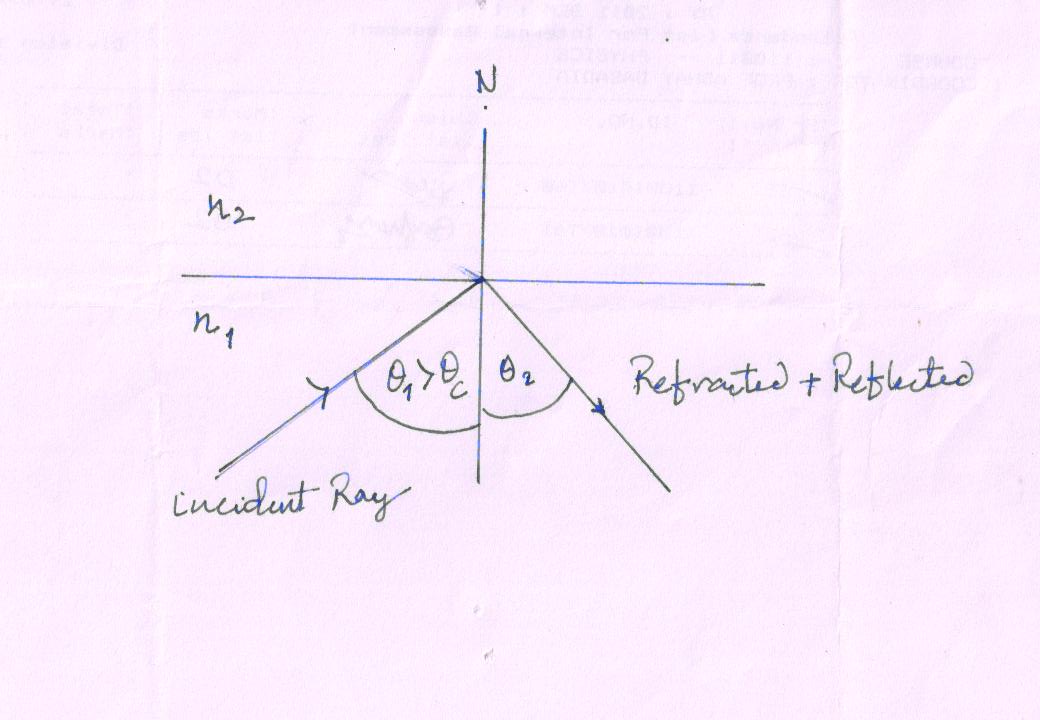
Fig 19(3c).
Thus,
If θ1 < θc, the refracts into the rarer medium
If θ1 = θc, the ray just grazes the interface of rarer-to-denser media
If θ1 > θc, the ray is totally reflected (refracted + partial internal reflected) into the denser medium
The phenomenon in which the light is totally reflected from a denser-to-rarer medium boundary is known as total internal reflection.
Last modified: Friday, 3 January 2014, 10:13 AM