Site pages
Current course
Participants
General
Module 1: Basics of Agricultural Drainage
Module 2: Surface and Subsurface Drainage Systems
Module 3: Subsurface Flow to Drains and Drainage E...
Module 4: Construction of Pipe Drainage Systems
Module 5: Drainage for Salt Control
Module 6: Economics of Drainage
Keywords
12 April - 18 April
19 April - 25 April
26 April - 2 May
Lesson 10 Layout and Installation of Pipe Drains
10.1 Introduction
Although a subsurface drainage system is adequately designed and is staked out according to plan, it will not function satisfactorily unless properly installed and maintained. The trench should be dug to the specified grade, the bedding condition and width of the trench should be such as to prevent overloading of the pipe, good workmanship should be secured in laying the pipe and in making junctions, the cost of installation should be reasonable, and the drainage system should be mapped and properly recorded.
The classical method of pipe installation comprises marking the alignment and grade, excavating trenches, placing the pipes and envelope material, and backfilling the trenches. Field drains are now installed by drainage machines, either by trenchers or by trenchless machines, whereas concrete collectors are often installed with excavators. In addition to the mechanics of installation, the work planning, working conditions, and the supervision and inspection are also important (Cavelaars et al., 1994).
A variety of adverse field conditions may jeopardize the pipe drainage system if no special precautions are taken. Most of these hazardous conditions can be grouped as wet conditions. Examples are a high watertable, a high water level in the open main drain, a waterlogged top soil due to recent irrigation or rainfall, and a pipe drain crossing an irrigation canal. Sometimes, an appropriate choice of season may overcome many of these problems. The hazards of wet conditions include:
The internal erosion of soil resulting in siltation of the pipe;
The formation of a puddled soil around the pipe, with a low permeability and a high entrance resistance;
The dislocation of pipe and envelope material in the case of sloughing conditions.
A general principle of drain installation is to start at the downstream end so that any free water can drain away immediately. Thus a good drainage base should be secured, which implies that the collector should be in place and should be functioning before the start of the field drain installation. Also, the water level in the open drain should be below the pipe outlets, and the connection with the collector should be made before a field drain is installed.
10.2 Alignment and Grade
Experience is desirable in the proper location of pipe drains, but there are a few general rules (Schwab et al., 2005): (i) place the outlet at the best possible location; (ii) provide as few outlets as possible; (iii) layout the system with short mains and long laterals; (iv) use the available slope to best advantage, especially on flat land; (v) follow the general direction of natural water ways, particularly with mains and submains on land with considerable slope; (vi) avoid routes that result in excessive cuts; (vii) avoid crossing waterways except at an angle of 45º or greater; and (viii) avoid soil conditions that increase installation and maintenance costs.
The classical method of marking alignment and grade is by placing stakes in the soil at both ends of the drain line, with the top of the stakes at a fixed height above the future trench bed. The slope of the drain line is thereby implicitly indicated. A row of boning rods is placed in line (both vertically and horizontally) between the stakes, with an extension at the upstream end of the drain line, where the run of the drainage machine ends (Fig. 10.1). The boning rods are thus in a line parallel to the trench bed, and grade control can be
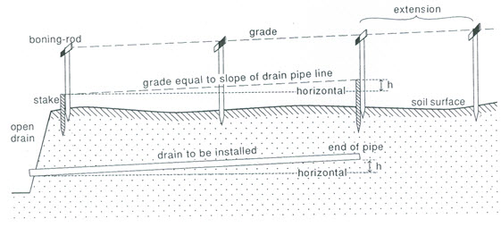
Fig. 10.1. Staking out for grade control of drain pipeline. (Source: Cavelaars et al., 1994)
achieved through sighting by the driver of the drainage machine (Fig. 10.2). The same principle can be applied when drains are installed manually.
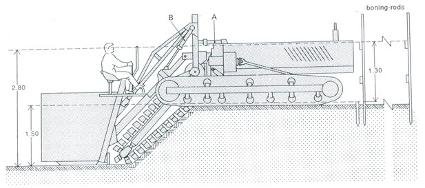
Fig. 10.2. Grade control by the operator. (Source: Cavelaars et al., 1994)
These days, most drainage machines have grade control by laser. An emitter, placed on a tripod near the edge of the field, establishes an adjustable reference plane over the field by means of a rotating laser beam (Fig. 10.3). A receiver, mounted on the digging part of the drainage machine, picks up the signal (Fig. 10.4). The control system of the machine continuously keeps a fixed mark in the laser plane. One position of the emitter can serve the installation of a fairly large number of drains.
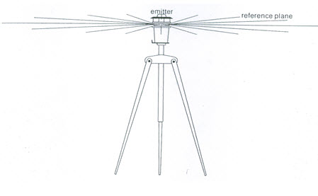
Fig. 10.3. Laser emitter establishes a reference plane. (Source: Cavelaars et al., 1994)
10.3 Drainage Machinery
The most common types of machines for installing field drains can be classified into two major types (Cavelaars et al., 1994): trenchers and trenchless machines.
10.3.1 Trenchers
Trench-excavating drainage machines vary from attachments to a wheel tractor, suitable for installation depths of up to 1 m, to heavy-duty machines, suitable for installing large-diameter collector pipes to a depth of about 3.5 m.
Most machines move on tracks, but especially the lighter ones may have rubber tyres. The digging implement is commonly a continuous chain with knives (Figs. 10.2 and 10.4). The excavation depth and trench width of a machine can be varied through interchanging digging attachments. The maximum depth of a trencher is somewhere between 1 and 3.5 m. The trench width varies roughly between 0.12 and 0.65 m, a standard width for field drains being 0.20 to 0.25 m. The engine power ranges from 75 to 300 kW (100 to 400 hp), and one machine weighs between 10 and 50 tons. The grade-control system is optional for most machines: either by the driver or by laser.
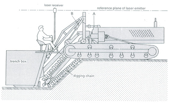
Fig. 10.4. Trencher equipped with laser-grade control. (Source: Cavelaars et al., 1994)
The corrugated plastic pipe for small-diameter field drains is carried on the machine on a reel and is fed into the trench. Larger-diameter corrugated pipes (e.g., for collectors) are usually laid out and coupled in the field beforehand. The continuous tube is subsequently picked up by the machine as it moves along. Clay tiles and concrete pipes move down a chute behind the digging chain. Synthetic and organic envelopes are usually pre-wrapped around the corrugated pipe. For gravel envelopes, a hopper can be fitted into which the gravel is fed from a trailer moving alongside the drainage machine. For a complete gravel surround, two gravel hoppers can be installed: one before and one after the point where the pipe is fed in.
Special trencher-machine attachments are water tank with a spraying nozzle to wet the chain (in sticky clay), and a scratcher at the back of the machine for blinding the pipe with soil from pre-selected layer (mostly well-structured top soil).
10.3.2 Trenchless Drainage Machines
Trenchless drainage machines have been used since about 1965, after flexible corrugated plastic pipe appeared on the market. Two main types of trenchless devices are: vertical plough (Fig. 10.5) and V-plough (Fig. 10.6).
A vertical plough acts as a subsoiler: the soil is lifted and large fissures and cracks are formed. If these extend down to the drain depth, the increased permeability leads to a low entrance resistance and an enhanced inflow of water into the pipe. Beyond a certain critical depth, however, the soil is pushed aside by the plough blade, instead of being lifted and fissured. This results in smearing, compaction and a destruction of macropores, so that the permeability is reduced and the entrance resistance is increased. The critical depth depends mainly on the soil texture and on the water content during pipe installation.
The V-plough, which lifts a triangular ‘beam’ of soil while the drain pipe is being installed, has a hazard of deforming the corrugated pipe under the weight of the soil beam. The problem was found to occur in heavy alluvial clay soil in The Netherlands, but it can be solved by simple adjustments to the plough.
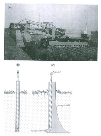
Fig. 10.5. Trenchless pipe drain installation: (A) Machine equipped with a vertical plough; (B) Rear view; (C) Side view. (Source: Cavelaars et al., 1994)
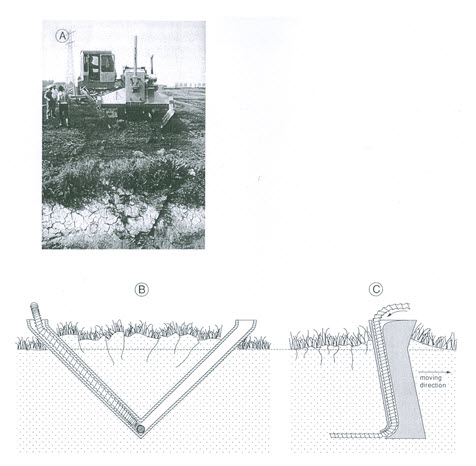
Fig. 10.6. Trenchless pipe drain installation: (A) Machine equipped with a V-shaped plough; (B) Rear view; (C) Side view. (Source: Cavelaars et al., 1994)
Corrugated plastic pipes are the only feasible pipes for trenchless machines. The V-plough can handle a maximum outside pipe diameter, including the envelope, of 0.10 to 0.125 m (Cavelaars et al., 1994). The vertical plough can handle much larger diameters. Although gravel envelopes would be possible with
trenchless drainage, it is not recommended because of the risk of a clogged funnel and because of the difficulty of supplying gravel to a comparatively fast-moving machine. The only practical option is to use pre-wrapped envelopes.
Table 10.1. Example of the capacity of a trencher (160 kW) and a trenchless machine with a V-shaped plough (200 kW) for the installation of field drains in singular systems in The Netherlands (Source: Van Zeijts and Naarding, 1990)
|
Sl. No. |
Soil Type |
Drain Depth (m) |
Capacity (m/h) |
Ratio Trenchless/Trencher |
||||||
|
Trencher |
Trenchless |
|||||||||
|
1 |
Sand |
1.00 |
700 |
840 |
1.2 |
|||||
|
2 |
1.30 |
600 |
600 |
1.0 |
||||||
|
3 |
1.60 |
520 |
430 |
0.8 |
||||||
|
4 |
1.90 |
475 |
- |
- |
||||||
|
5 |
Clay loam and clay |
1.00 |
620 |
1150 |
1.9 |
|||||
|
6 |
1.30 |
540 |
1050 |
1.9 |
||||||
|
7 |
1.60 |
470 |
800 |
1.7 |
||||||
|
8 |
1.90 |
420 |
- |
- |
||||||
Because of the high speed, depth regulation by laser is the only practical method for trenchless machines. Furthermore, visual inspection is impossible due to the absence of an open trench. The advantage of trenchless installation decreases rapidly with greater drain depth and with higher soil resistance.
10.4 Backfilling
Backfilling of the trench can be accomplished with many machines such as bulldozers, hoes, motor graders, manure loaders, and blades on small tractors. All soil should be replaced and heaped up so that after settlement the trench can be crossed with tillage equipment. If the soil is dry or contains stones, extreme care should be taken to prevent breakage of the tile or crushing of the plastic tubing.
10.5 Installation of Collector Drain
Concrete pipes are installed either by trencher or by hydraulic excavator (backhoe). As a safeguard against siltation, the collector is commonly constructed as a closed conduit. Thus, the joints between pipe sections are sealed with either mortar or close-fitting rubber rings.
The larger corrugated plastic pipes (>0.20 m diameter) need to be embedded in gravel as a protection against deformation, and are comparatively expensive, although their use is increasing. They are the only alternative if a de-watering collector is needed. The installation of such a collector is commonly done by a trencher. The gravel bed also has a hydraulic function as well as a filter function.
Installing a deep collector in an unstable soil well below the water is a difficult job, because of the sloughing conditions during pipe installation. Installing concrete pipes is then only possible after the soil has been de-watered (i.e., by lowering the waterable to below the installation depth of the collector). This can be achieved by the classical well-pointing technique or, alternatively, by horizontal dewatering (Cavelaars et al., 1994).
10.6 Operation and Maintenance
Once a drainage system has been installed, we have to ensure that it will function properly for a long time. Technically, this requires that a good drainage base is maintained, that the system is inspected regularly, and that repairs and cleaning are done when necessary. Administratively, responsibilities for operation and maintenance must be well-defined, and an adequate budget must be available. In large drainage projects, it is common that upon completion of the drainage works, the responsibility for the system is transferred from a construction agency to an operation or maintenance agency.
References
Cavelaars, J.C., Vlotman, W.F. and Spoor, G. (1994). Subsurface Drainage Systems. In: H.P. Ritzema (Editor-in-Chief), Drainage Principles and Applications, ILRI Publication 16, International Institute for Land Reclamation and Improvement (ILRI), Wageningen, The Netherlands, pp. 827-929.
Schwab, G.O., Fangmeier, D.D., Elliot, W.J. and Frevert, R.K. (2005). Soil and Water Conservation Engineering. Fourth Edition, John Wiley and Sons (Asia) Pte. Ltd., Singapore.
Van Zeijts, T.E.J. and Naarding, W.H. (1990). Possibilities and Limitations of Trenchless Pipe Drain Installation in Irrigated Areas. In: Installation of pipe drains, Government Service for Land and Water Use, Information Paper 21, Utrecht, pp. 10-22.
Suggested Readings
Bhattacharya, A.K. and Michael, A.M. (2003). Land Drainage: Principles, Methods and Applications. Konark Publishers Pvt. Ltd., New Delhi, India.
Murty, V.V.N. and Jha, M.K. (2011). Land and Water Management Engineering. Sixth Edition, Kalyani Publishers, Ludhiana, India.
Ritzema (Editor-in-Chief) (1994). Drainage Principles and Applications. International Institute for Land Reclamation and Improvement (ILRI), ILRI Publication 16, Wageningen, The Netherlands.
Schwab, G.O., Fangmeier, D.D., Elliot, W.J. and Frevert, R.K. (2005). Soil and Water Conservation Engineering. Fourth Edition, John Wiley and Sons (Asia) Pte. Ltd., Singapore.
Last modified: Monday, 16 September 2013, 11:34 AM