Site pages
Current course
Participants
General
Module 1_Fundamentals of GW
Module 2_Well Hydraulics
Module 3_Design, Installation and Maintenance of W...
Module 4_Groundwater Assessment and Management
Module 5_Principle, Design and Operation of Pumps
Module 6_Performance Characteristics, Selection an...
Keywords
12 April - 18 April
19 April - 25 April
26 April - 2 May
Lesson 18 Methods for Constructing Deep Wells
18.1 Introduction
Construction of ‘deep wells’ (wells with depths more than 15 m) having high capacity as well as large diameter and depth is generally accomplished by using drilling methods. Various drilling methods used for constructing deep wells can be classified as: (i) Percussion drilling (also known as ‘Cable tool drilling’), (ii) Rotary drilling, and (iii) Rotary-Percussion drilling (or ‘Rotary-cum-Hammer drilling’). Each method has particular advantages under favorable hydrogeologic conditions; experienced drillers can easily select a suitable method for a given hydrogeologic setting. Brief descriptions of these drilling techniques are given below, whereas Table 18.1 summarizes the performance of these drilling techniques in diverse geologic formations. The construction procedure of a successful well is dependent on local conditions encountered during drilling, and hence the construction of each well should be treated as an individual project (Todd, 1980).
Table 18.1. Performance of drilling methods in different types of geologic formations (Source: Todd, 1980)
|
Sl. No. |
Type of Geologic Formation |
Performance of Drilling Methods |
||
|
Percussion |
Rotary |
Rotary-Percussion |
||
|
1 |
Dune Sand |
Difficult |
Rapid |
Not Recommended |
|
2 |
Loose Sand and Gravel |
Difficult |
Rapid |
Not Recommended |
|
3 |
Quicksand |
Difficult, except in thin streaks. Requires a string of drive pipe. |
Rapid |
Not Recommended |
|
4 |
Loose boulders in Alluvial Fans or Glacial Drift |
Difficult; slow but usually can be handled by driving pipe. |
Difficult, Frequently Impossible |
Not Recommended |
|
5 |
Clay and Silt |
Slow |
Rapid |
Not Recommended |
|
6 |
Firm Shale |
Rapid |
Rapid |
Not Recommended |
|
7 |
Sticky Shale |
Slow |
Rapid |
Not Recommended |
|
8 |
Brittle Shale |
Rapid |
Rapid |
Not Recommended |
|
9 |
Sandstone (poorly cemented) |
Slow |
Slow |
Not Recommended |
|
10 |
Sandstone (well cemented) |
Slow |
Slow |
Not Recommended |
|
11 |
Chert Nodules |
Rapid |
Slow |
Not Recommended |
|
12 |
Limestone |
Rapid |
Rapid |
Very Rapid |
|
13 |
Limestone with chert nodules |
Rapid |
Slow |
Very Rapid |
|
14 |
Limestone with small fractures |
- |
- |
Very Rapid |
|
15 |
Limestone (cavernous) |
Rapid |
Slow to Impossible |
Difficult |
|
16 |
Dolomite |
Rapid |
Rapid |
Very Rapid |
|
17 |
Basalts, thin layers in sedimentary rocks |
Rapid |
Slow |
Very Rapid |
|
18 |
Basalts, thick layers |
Slow |
Slow |
Rapid |
|
19 |
Metamorphic Rocks |
Slow |
Slow |
Rapid |
|
20 |
Granite |
Slow |
Slow |
Rapid |
18.2 Percussion Drilling
Percussion drilling is also known as ‘cable tool drilling’ or ‘standard drilling’, and it is accomplished with the help of a standard well-drilling rig, percussion tools and a bailer. Basically, the drilling procedure involves a regular lifting and dropping of a string of tools. On the lower end, a drill bit breaks/cuts the rock or other earth materials by impact. Thus, by repeated pounding and breaking/cutting operations, a borehole is formed. In particular, the percussion drilling equipment consists of a tool string (comprising a rope/swivel socket, a set of drilling jars, a drill stem, and a drill bit) suspended by a cable from a walking beam (truck mounted or tripod) or operated from a diesel engine, which lifts and drops the tool string (Fig. 18.1). Thus, the percussion/cable tool drilling rig consists of a mast, a multiline hoist, a walking beam and an engine. In modern designs, the entire assembly is truck mounted for easy portability.
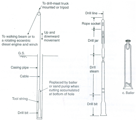
Fig. 18.1. Percussion drilling setup. (Source: Raghunath, 2007)
The most important part of the tool string is the drill bit (having a sharp chisel edge) which crushes/breaks almost all types of earth materials. The length of drill bits varies from 1 to 3 m and they weigh up to1500 kg (Todd, 1980). Drill bits of various shapes are manufactured for drilling in different subsurface formations. The drill stem is a long steel bar that provides additional weight to the bit and its lengths helps in maintaining a straight vertical hole while drilling in hard rock. Drilling jars consist of a pair of narrow linked steel bars and help in loosening the tools when they stick in the hole. Under normal tension on the drilling line, the jars remain fully extended. When tools get stuck, the drilling line is slackened and then lifted upward. This causes an upward blow to the tools because of which tools are released. Swivel/rope socket connects the tool string to the cable. The wire cable, which carries and rotates the drilling tool on each upstroke, is known as drill line (Fig. 18.1).
Drill cuttings are removed from the well by a bailer or sand bucket (Fig. 18.1). A bailer consists of a section of pipe with a valve at the bottom and a ring at the top for attachment to the bailer line. The valve allows the cuttings to enter the bailer but prevents them from escaping. After filling, the bailer is hoisted to the surface and emptied. Drilling is accomplished by regular lifting and dropping of the tool string. As a result, the drilling line is rotated, the drill bit forms a round hole through the formation, the tool string is lifted and the hole is bailed. The cable tool method is capable of drilling holes of 8 to 60 cm in diameter through consolidated rock materials to depths of 600 m (Todd, 1980). It is least effective in unconsolidated sand and gravel formations, especially quicksand, because the loose material slumps and caves around the drill bit (Table 18.1).
Some of the advantages of the percussion drilling method are: (a) It is highly versatile in its ability to drill satisfactorily over a wide range of geologic conditions; (b) minimum water is required for drilling, a matter of concern in arid and semi-arid regions; (c) reasonably accurate sampling and logging of the formation material can be readily achieved; (d) the simplicity of design, ruggedness, and easy maintenance and repair of the rigs and tools are important advantages in isolated areas; and (e) rough checks on the water quality and yield from each water-bearing stratum can be made as drilling progresses. On the other hand, major drawbacks of the percussion drilling method are: (a) Slower drilling rate, (b) limitation of the drilling depth, (c) necessity of driving casing coincidentally with drilling in unconsolidated geologic formations, and (d) difficulty in pulling casing from deep boreholes.
18.3 Rotary Drilling
Rotary drilling method is a rapid method for drilling in unconsolidated formations. It consists of a rotating drill bit for cutting the borehole with a continuously circulated drilling fluid (usually a mixture of water and bentonite). The drilling fluid is forced through the hollow drill pipe on to the drill bit by a mud pump for removing the materials loosened by the drill bit (i.e., cuttings). The cuttings are carried upward in the hole by the rising mud, which flow to a settling pit where the cuttings settle out and the mud fluid overflows to a storage pit from where it is recirculated again (Fig. 18.2). The mud forms a clay lining on the wall of the borehole, which provides an adequate support for the wall of the hole, and hence casing is not normally required during drilling. The rotary drilling rig consists of a mast (derrick), a hoist, a power-operated revolving table that rotates the drill stem and bit, a pump for drilling mud, and an engine.
Deep wells up to 45 cm in diameter, and even larger with a reamer, can be constructed by the rotary drilling method (Todd, 1980). Drill bits for rotary drilling are available in different forms and commonly used designs are: (a) fishtail drill bit, (b) cone-type rock drill bit, and (c) carbide button drill bit as shown in Fig. 18.3.
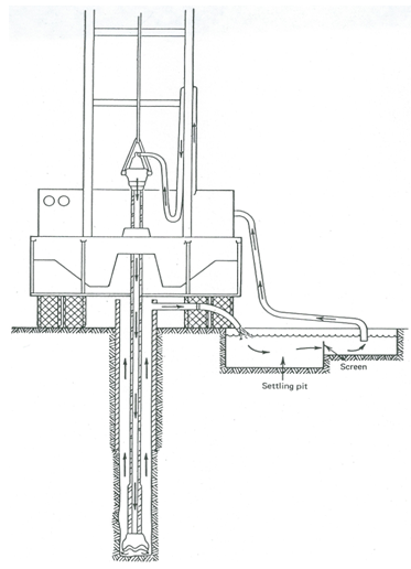
Fig. 18.2. Drilling mud circulation system for the rotary method. (Source: Todd, 1980)
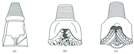
Fig. 18.3. Common types of rotary drill bits: (a) Fishtail drill bit, (b) Cone-type rock drill bit, (c) Carbide button drill bit. (Source: Todd, 1980)
The speed of rotation of drill bit in the borehole is 30 to 60 rpm. Drilling mud is essentially bentonite clay and the density of the mud fluid varies from 1.02 to 1.14 g/cm3. The upward velocity of flow in the borehole is 0.7 to 1 m/s (Raghunath, 2007).
Initially, rotary drilling was employed for drilling oil wells and its application to water-well drilling has gradually increased over the years. The main advantages of the rotary drilling method are: (a) fast drilling rate, (b) no requirement of casing during drilling, and (c) the convenience for electric logging. There are also some disadvantages of this drilling method, which are: (a) high equipment cost, (b) more complex operation, (c) necessity to remove mud cake (clay lining) during well development, and (d) the problem of lost circulation in highly permeable or cavernous geologic formations.
18.3.1 Air Rotary Method
Rotary drilling can also be done using compressed air instead of drilling mud. This technique is rapid and convenient for small-diameter holes in consolidated geologic formations (e.g., fractured rocks) where a clay lining is not required to support the walls against caving. Large-diameter holes can be drilled by employing foams and other air additives (Todd, 1980). It can be used for drilling wells to the depth of more than 150 m under favorable conditions.
Air rotary drilling is used in fractured/fissured rocks and is especially suitable for limestones. A striking feature of the air rotary drilling is its ability to drill consolidated geologic formations with little or no water.
18.3.2 Reverse-Circulation Rotary Method
The reverse-circulation rotary method is a modified form of the standard rotary method of drilling. In this method, the direction of water flow is reversed, i.e., from the annular space between the drill pipe and the wall of the hole through the drill bit into the hollow drill pipe upwards and discharged by a large-capacity pump into a large settling pit where cuttings settle out. The clear water returns to the borehole by gravity flow (Fig. 18.4). Relatively high velocity of water in the drill pipe (usually >2 m/s) enables the cuttings to be carried to the ground surface without the use of clay or other additives; the use of additives will increase viscosity which is not desirable for this method.
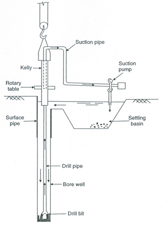
Fig. 18.4. Hydraulic rotary drilling with reverse circulation.
(Source: Raghunath, 2007)
In this system, drilling is done without a casing and hydrostatic pressure is used to support the walls of a borehole during drilling. Water level in the borehole is maintained at about 2 m above natural level or at ground level. The settling pit is about three times the volume of the material to be removed from the borehole. The diameter of the borehole is large compared to the drill pipe so that the velocity of the descending water in the annular space is low (≤ 30 cm/s), and the drill bit and drill pipe are rotated at speeds ranging from 10 to 40 rpm (Raghunath, 2007). The diameter of drill bits varies from 0.4 to 1.8 m. The reverse-circulation rotary rigs generally can drill to depths of 125 m; though suitable modifications with air-lift pumping can substantially increase this depth limit (Todd, 1980).
The reverse-circulation rotary method has become increasingly popular for drilling large-diameter boreholes in unconsolidated geologic formations. In fact, it is the most rapid drilling technique available for unconsolidated formations. The large diameters facilitate completion of the wells by artificial gravel packing. The minimum borehole diameter should be about 40 cm in order to avoid the erosion of the sides of the borehole (Todd, 1980), thereby restricting the downward velocity of the water in the borehole. The main disadvantage of this method is that it requires a large quantity of water to be readily available.
18.4 Rotary-Percussion Drilling
This method of drilling combines the percussion effect of cast tool drilling and the rotary action of rotary drilling. It is also known as ‘Rotary-cum-Hammer drilling’. It uses compressed air as the drilling fluid which provides the fastest method for drilling in hard-rock formations (Todd, 1980); it can drill 15-20 cm holes to a depth of 120 m in 10-15 hours (Raghunath, 2007). A rotating drill bit, with the action of a pneumatic hammer delivers 10 to 20 impacts (blows) per second to the bottom of the hole. The diameter and depth of the hole is limited by the volume of air that can be exhausted through the hammer to remove the cuttings. A flush pump is used for flushing the hole and bringing the cuttings to the ground surface. Air compressor, pump and prime mover are usually mounted on a truck.
Compressed air must be supplied at a pressure of 750 to1350 kN/m2 (to effectively remove the cuttings) and free air supply of at least 9 to 10 m3/min for drilling 15-cm holes. The upward velocity in the space outside the drill pipe should be about 900 m/min. The rotation speed of the drill bit should be from 15 to 50 rpm (Raghunath, 2007). Reduced speed is required for drilling in harder and more abrasive rocks. In case of caving formations or incidence of large quantities of water, this method is not suitable. In this situation, the conventional rotary drilling with mud as a drilling fluid works satisfactorily (Todd, 1980).
References
-
Raghunath, H.M. (2007). Ground Water. Third Edition, New Age International Publishers, New Delhi.
-
Todd, D.K. (1980). Groundwater Hydrology. John Wiley & Sons, New York.
Suggested Readings
-
Todd, D.K. (1980). Groundwater Hydrology. John Wiley & Sons, New York.
-
Raghunath, H.M. (2007). Ground Water. Third Edition, New Age International Publishers, New Delhi.
-
Michael, A.M. and Khepar, S.D. (1999). Water Well and Pump Engineering. Tata McGraw-Hill Publishing Co. Ltd., New Delhi.
-
Sarma, P.B.S. (2009). Groundwater Development and Management. Allied Publishers Pvt. Ltd., New Delhi.
Last modified: Friday, 14 March 2014, 11:26 AM