Site pages
Current course
Participants
General
Module 1. Micro-irrigation
Module 2. Drip Irrigation System Design and Instal...
Module 3. Sprinkler Irrigation
Module 4. Fertigation System
Module 5. Quality Assurance & Economic Analysis
Module 6. Automation of Micro Irrigation System
Module 7. Greenhouse/Polyhouse Technology
12 April - 18 April
19 April - 25 April
26 April - 2 May
Lesson 27. Types of Controls and Automation in Micro Irrigation
Automatic micro irrigation/drip irrigation ensures optimum soil moisture at root zone of the crop and throughout crop growth season for healthiest growth. This involves complete understanding of irrigation of irrigation scheduling, which is a function of soil plant and weather parameters. The control systems are designed to accomplish automation using these parameters. In this lesson basic control theory relevant to micro irrigation and types of automating micro irrigation are dealt
27.1 Automation Controls
The control theory or system analysis of mathematical techniques used to model how one component controls the activity of another component is an inter linked system. The control systems are divided in to two categories:
i) Open loop control (OLC)
ii) Closed loop control (CLC)
27.1.1 Open loop control (OLC)
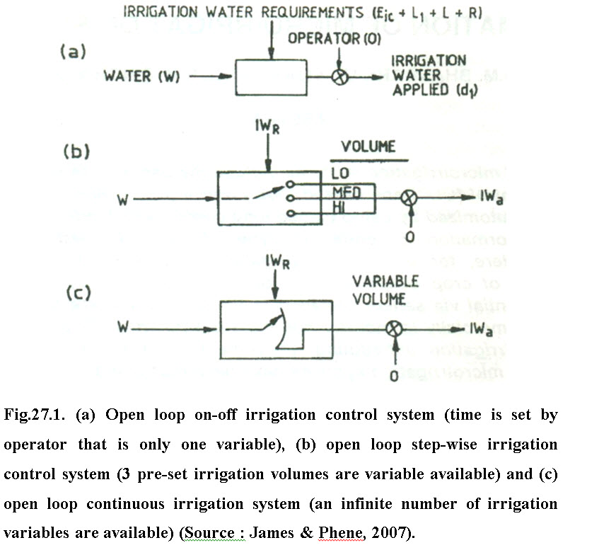
In an open loop control system, the operation is pre-set and independent of any sensor input with an operator making the decision. In irrigation scheduling program, two decisions are used: i) When to irrigate and ii) how much to irrigate. The operation of an open loop control for operating irrigation system is shown through Fig. 27.1.
27.1.2 Closed loop control (CLC)
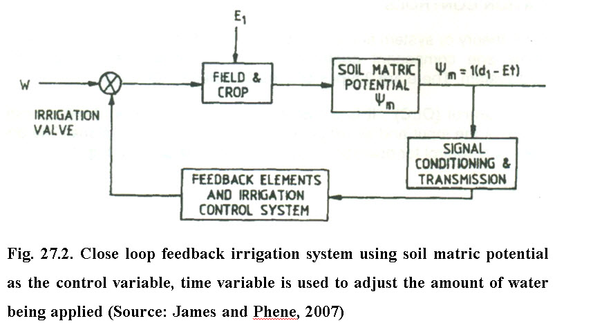
In this system, the input is directly dependent on the output through a feedback mechanism from the output to the input. By having closed to compare the output with some reference input signal (pre-set value) so that the precise control can be achieved. The closed loop control operation installed for controlling irrigation system is given in Fig.27.2. The crop evaporation (ETc) is measured directly by using lysimeter using a sensor and this information is used to adjust the irrigation volume or time so that the depth of irrigation water (di) is proportional to Etc such that
di = Etc/Ea (27.1)
where, Ea = application efficiency of irrigation system
Within OLC and CLC, three control modes used are: i) On- off control; ii) Step- wise control and iii) continuous control. Brief description of these control modes are presented below:
i) On-off control: The on-off control makes the irrigation system on or off, and the control condition is independent of the system. Fig. 27.1(a) shows a block diagram of this control system where the valve is on or off. Most of the irrigation systems are controlled by this mode. In some cases, the operator is replaced by the timer switch or more sophisticated electronic devices. However, the control condition remains independent of the system.
ii) Step-wise control: In step-wise control 27.1(b), di may be varied by selecting different positions on a valve, a flow meter, or a timer to give different irrigation volumes. For example, early in season where Etc is low, position Lo could be used. As Etc increases, position Med and HI could be selected to increase di and progressively apply more water with each irrigation.
The application of step-wise control in irrigation is sometimes implemented by a time clock with fixed intervals of time control, but operates exactly like the on-off control. The irrigation time (Ti) can be calculated from the relation
Ti = 100 (Etc×If) / (Ei × la) (27.2)
Where, Ti = irrigation time, h
lf = irrigation frequency, days / irrigation
la = application rate of irrigation system, mm h-1
Etc can be adjusted for both leaching and percolation losses by multiplying Etc with appropriate correction factor.
iii) Continuous control: In continuous control (Fig. 27.1. c) can be selected from minimum to maximum values by adjusting time or volume of water in a continuous manner. Any value of time or volume can be set in the flow meter.
27.2 Volume-Based Automated Irrigation System
In volume-based system, the preset amount of water can be applied in the field segments by using automatic volume controlled metering valves. Automation using volume-based systems are of two types. In first type of system, automatic metering valve with pulse output provides one pulse after completing one dial of the automatic metering valve. The dial capacity may vary. The volume-based controller accepts the pulse input from the valve and counts the volume per pulse. The volume of water required for each segment can be programmed in the controller. Thus by counting the number of pulse received by the controller, it can count the volume of water passed through. After providing required volume of water through first valve, the first valve, it closes down controller, then switch on the next valve in the sequence. In second type of system, no controller is required. Automatic metering valves are positioned near each field segment. All automatic metering valves are interconnected in series with the help of control tube. For automatic closing and opening of the metering valves with the help of water pressure signal, components like T- connector, shuttle valve and a 3 way relay (called shastomit) are also installed along the circuit. During sequential operation only one automatic metering valve remains open. The next valve in the series opens after the first valve closes.
27.3 Time Based Automated Irrigation System
In time based system, time is the basis of irrigation. Time of operation is calculated according to volume of water required and the average flow rate of water. The first thing to perform before programming for time-based system is to determine the duration of irrigation required for each section. The duration of individual valves has to be fed in the controller along with system start time, also the controller clock is to be set with the current day and time. As the clock of the controller knocks the start time of programme, it starts sending signals to the first automatic valve in the programme sequence, the pump also starts up at the same time. As soon as duration of first valve is over the controller either stops or switches on to next valve. When the operation of last valve is over, controller stops sending signals to valves and pump. The same process is repeated at next run time.
27.4 Real Time Feedback System
Real time feedback is the application of irrigation based on actual dynamics demand of the plant itself, plant root zone effectively reflecting all environmental factors acting upon the plant. Operating within controlled parameters, the plant itself determines the degree of irrigation required. Various sensors, viz. tensiometers, relative humidity sensors, rain sensors, temperature sensors etc. control the irrigation scheduling. These sensors provide feedback to the controller to control its operation.
27.5 Sequential and Non Sequential Automated Irrigation System
27.5.1 Sequential System
On the basis of type of control, the automated irrigation systems can be classified in to two categories: sequential and non- sequential type. In sequential systems the field in divided in to different sub-units, which is irrigated one after the other in particular sequence. Whereas in the non-sequential systems the sub-units are irrigated randomly based on the plant water needs and operated electrically with or without programming with possibility of utilizing feedback information from the field for remote control.
A sequential system can be operated
i) Hydraulically operated
ii) Electrically operated
iii) Combination of both hydraulically or electrically operated.
i) Sequential hydraulically operated automated irrigation system
The sequential system is particularly suited for low discharge rates irrigation through small diameter tubing. At each connection to the main line (except at the end last connection) a water metering valve unit and a hydraulic valve are installed. At the beginning of the irrigation cycle the metering valves are set for the required volume of water to be supplied to the field. The amount of water is set based on the type of the crop, soil and climatic conditions. Such type of automation is suitable for greenhouse nurseries irrigation.
ii) Sequential electrically operated system (Time based)
Sequential electrically operated systems operate the remotely placed solenoid valves in sequence using electricity. In this system, the water delivered to different plots is regulated by a timer clock, which is programmed to start and stop at desired time by the user. These types of controllers are usually designed with calendar programs so that the watering cycle can be automatically started on the desired day of the week. The controllers have seven or fourteen days calendar program. This type of system is used for irrigation of irrigation of domestic gardens.
27.5.2 Non-Sequential Systems: Hydraulic/Electric valves
Electrically controlled non-sequential systems are fully automatic to a greater extent as compared to that of sequential systems. Water in each unit can be supplied in different quantity and valve opens at a different time in response to a predetermined program or to soil water content. The control panel consists of programmed electrical circuits to operate the pump or main valve, to add fertilizer according to a pre-set schedule and or to apply irrigation as per crop need and soil moisture. Such systems are also remote-controlled, and are designed for feedback of the data received from the field so that automatic regulation can be done and adjustments for changes in the pressure and discharge rate of the supply line can be made. This type of system is used for high pressure discharge. Solenoid valves serve only as control to activate hydraulic valves and the overall operation is hydraulic electric. Rest of its operation is similar to sequential electrically operated systems.
Non-sequential systems are further classified into three categories:
(i) Feedback control
(ii) Inferential control
(iii) Combination of above two methods with time based control
27.5.2.1 Feedback control system (Soil moisture based)
The main components of the feedback control system are sensors for soil moisture, weather monitoring parameters, electronic control unit (comparators /microprocessor/computer) and solenoid valves. A farm is divided in to different sub-units. Each sub-unit has one soil moisture sensor. The sensors are connected through interfacing circuit to the central control unit, which could be a microprocessor or a computer with a program to schedule irrigation a or comparator circuit. Based on the soil moisture status (measured by soil moisture sensor) of a sub-unit the decision to start and stop irrigation is taken by the controller. The electronic controller actuates and de-actuates solenoid valves to start and stop the irrigation respectively through proper interfacing circuit and relay switches (Joshi et al., 2002).
Soil moisture based Automated Irrigation Controller developed at IIT Kharagpur (Joshi et al., 1999) uses a tensiometer connected with a U-tube manometer to activate/deactivate irrigation pump. In this system irrigation is given to unit area considering homogeneous soil condition.
Luthra et al. (1996) developed an automatic valve for irrigation operation. The soil water tension is sensed through modified tensiometer which generates electrical signal. The output of tensiometer is processed for operation of D.C. operated bidirectional motor at present values of soil water tension which is coupled to the gate valve. This valve can be fitted with mains, sub-mains or individual laterals of drip irrigation setup. Through automatic operation of valve, required amount of irrigation is applied which maximizes the water use efficiency of the system. After meeting the irrigation requirement of crop a signal is generated through a preprogrammed timer (designed suitably for this purpose) for closing the valve.
Testezlaf et al. (1997) developed automated irrigation computer control system for management of greenhouse container plants. The system consisted of soil moisture sensors, a hardware input/output interface (A/D card), a computer with a software interface, and actuators. The evaluation results show that the control system is reliable in applying water responding to the plant demands.
27.5.2.2 Inferential control system
The main parts of inferential control system are sensors for measuring various climatological parameters such as solar radiation, maximum and minimum temperature, wind speed, relative humidity, pan evaporation etc.
This system makes use of various evapotranspiration models to estimate evapotranspiration of crop using different climatological parameters. The estimated evapotranspiration is used to schedule irrigation. The solenoid valves are operated using interfacing circuit and relay switches to put on or to put off the irrigation system.
Koe et al. (2000) developed and tested an automated cycled over tree sprinkler irrigation system in a 0.4 ha (1 acre) dwarf apple orchard to protect apple buds from cold temperatures. The control system hardware components used in the experiment included sensor for measuring air temperature, wind speed, wind direction, relative humidity data, a microcomputer, data acquisition system, control boards and the irrigation system.
27.5.2.3 Combination of Both
Noble et al. (2000) developed and tested two automated drip irrigation systems: one based on soil electrical conductivity and the other based on leaf-air temperature difference of Okra (Abelmosolus esculentus) crop. Sensors were evaluated for monitoring the soil moisture content based on electrical resistance variation with moisture content. The sensor with washed sand as porous medium was found to be the most efficient one among the other materials. A low cost, commercially available button type thermistor was used as the leaf and air temperature sensors. Variation of moisture in soil causes variation in electrical resistance across the electrode of the sensor. The electrical signal obtained by variation in the electrical resistance is processed by the circuit and operates the relay contacts connected to a 12 volt DC operated normally closed solenoid valve. When the soil gets dry and its resistivity increases, the circuit opens the valve and water flows to the plants. As water content in soil reaches the required level set by a variable resistance, the solenoid valve closes. The difference of voltage between the two thermistors (one attached to plant leaf and other exposed to atmosphere) was used for starting irrigation through the solenoid valve for a fixed duration using IC 555 and 12 volt relay. The amount of water applied per day, leaf-air temperature and soil moisture content can be monitored. The system maintained the designed soil moisture content and air-leaf temperature differential of the crop.
Reference:
James E.A., and Phene C.J., 2007 Automation in Micro irrigation for crop Production, Design Operation and Management, Chapter 7 edited by Freddie R Lamn, James E Ayars and Francis, S. Nakayama, Elsevie Publication : 259-281.
Joshi Ajay, Tiwari K. N, Banerjee S. 1999 Automated Irrigation Controller
Patent No. # 6/Cal/99 dated 04-1-1999, IIT Kharagpur.
Joshi Ajay, Tiwari K. N, Banerjee S. 2002, Low Cost Computer Controlled Automated Irrigation System. Patent No. # 307/Cal/2002 dated 15-5-2002, IIT Kharagpur
Koe, A.B., P.H. Heinemann and R.M. Crassweller. 2000. Automated cycled sprinkler irrigation system for frost protection of apple buds. Applied Engineering in Agriculture, 16(3): 231-240.
Luthra S.K., M.J. Kaledhonkar and S.K. Gupta. 1996. Design and development of a valve with automatic controls for drip irrigation system. Seminar Proceedings IE(I) Agricultural Engineering Division, Karnataka State Centre. All India Seminar on Modern Irrigation Techniques, Bangalore, June 26-27: 53.
Suggested Reading
Phene, C.J., C.P. Allee and J. Pierro. 1988. Measurement of Soil matric Potential and Real Time Irrigation Scheduling. International Proceedings of Conference on Sensors & Techniques for Irrigation Management, Center for Irrigation Technology. Publication 880502, Fresno, California State University, 63-75.
Testezlaf, R., F.S., Zazueta and T.H. Yeager. 1997. A real-time irrigation control system for greenhouses. Applied Engineering in Agriculture, 13(3): 329.
Last modified: Monday, 20 January 2014, 11:24 AM