Site pages
Current course
Participants
General
Module 1: Introduction and Concepts of Remote Sensing
Module 2: Sensors, Platforms and Tracking System
Module 3: Fundamentals of Aerial Photography
Module 4: Digital Image Processing
Module 5: Microwave and Radar System
Module 6: Geographic Information Systems (GIS)
Module 7: Data Models and Structures
Module 8: Map Projections and Datum
Module 9: Operations on Spatial Data
Module 10: Fundamentals of Global Positioning System
Lesson 8 Stereoscopy and Photogrammetry
8.1 Definition of Stereoscopy
Stereoscopy, sometimes called stereoscopic imaging, is a technique used to enable a three dimensional effect, adding an illusion of depth to a flat image. In aerial photography, when two photographs overlap or the same ground area is photographed from two separate position forms a stereo-pair, used for three dimension viewing. Thus obtained a pair of stereoscopic photographs or images can be viewed stereoscopically. A stereoscope facilitates the stereoviewing process by looking at the left image with the left eye and the right image with the right eye. It is based on Porro-Koppe’s Principle that the same light path can be generated in an optical system if a light source is projected onto the image taken by an optical system. Stereoscopic vision is constructed with a stereopair images using the relative orientation or tilt at the time of photography. Stereo viewing allows the human brain to judge and perceive in depth and volume. 3D representation of the earth’s surface resulting in the collection of the geographic information with a greater accuracy compared to the monoscopic techniques.
8.2 Stereoscopic Vision
On our daily life we unconsciously perceive and measure depth using our eyes. This stereo effect is possible because we have two eyes or binocular vision. The perception of depth through binocular vision is referred to as stereoscopic viewing, which means viewing an object from two different locations. Monoscopic or monocular vision refers to viewing surrounding objects with only one eye. Depth is perceived primarily based on the relative sizes of objects, shadow; distant objects appear smaller and behind closer objects. In stereoscopic vision, objects are viewed with both eyes a little distant from each other (approximately 65 mm) helps in viewing objects from two different positions and angles, thus a stereoscopic vision is obtained. The angle between the lines of sight of two eyes with each object known as parallactic angle helps our brain in determining the relative distances between objects. Lesser the parallactic angle higher the objects depth. Figure 8.1 shows the human stereoscopic vision, parallactic angle Øa > Øb, helps the brain automatically to estimate the differences (Da - Db) in depths between the objects A and B. This concept of distance estimation in stereoscopic vision is applied to view a pair of overlapping aerial photograph.
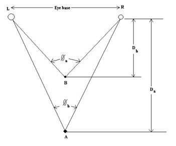
Fig. 8.1. Human stereoscopic vision.
As an example, in two photographs overlap the same region, in which objects A, B and C are situated at the same altitude and object D at a different altitude, the four objects will be observed in a different sequence in the two photographs a, b, d, c in the left photograph and a, d, b, c in the right (Fig. 8.2). In the same photograph, segments ab and bc are equal since they are at the same altitude, but segments ad and dc are not (source: Girard, 2003).
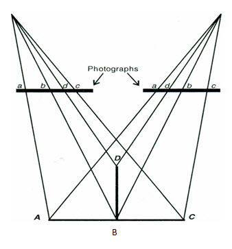
Fig. 8.2. Perception of relief from two aerial photographs.
(Source: Girard, 2003)
8.3 Stereoscopes
A stereoscope is used in conjunction with two aerial photographs taken from two different positions of the same area, (known as a stereo-pair) to produce a 3-D image. There are two types of stereoscopes: lens (or pocket) stereoscope and mirror stereoscope. Lens (or pocket) stereoscope has a limited view and therefore restricts the area that can be inspected where as in mirror stereoscope has wide view and enables a much larger area to be viewed on the stereo-pair. The most obvious feature when using a stereoscope is the enhanced vertical relief. This occurs because our eyes are only 65mm apart, but the air photos may be taken at 100s of meters apart, hence the difference in exposures is far greater than the difference between our eyes. Such an exaggeration also enables small features to become quite apparent and easily viewed.
A stereoscope (Fig. 8.3) consists of a double optical system (lenses, mirrors, prisms, etc.) mounted on a rigid frame supported on legs. In this way distance d is fixed and kept the focal distance. Thus the optical system creates a virtual image at infinity and consequently stereoscopic vision is obtained without eyestrain.
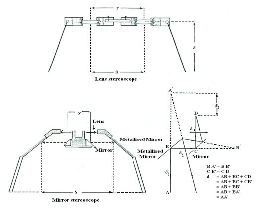
Fig. 8.3. Lens and mirror stereoscopes. (Source: Girard, 2003)
A simple lens stereoscope is made up of two achromatic convex lenses. The focal length is equal to d corresponding to the height of the stereoscope above the plane on which the stereo pair is placed. The lens spacing (y) can allowed varying within 45 to 75 mm to accommodate individual eye spacing. The disadvantage of lens stereoscope is that the features just underneath the lens only are viewable but it has some magnification power. A mirror stereoscope comprises two metallised mirrors, two prisms, two lenses and two eyepieces having little or no magnification power. It enables viewing the optical part fixed on an arm and the photographic pairs are arranged on two different planes. They facilitate analyses of several stereo pairs consecutively without changing the arrangement in the whole overlap region compared to the lens stereoscope.
8.4 Orientation of Photographs and use of Stereo Pairs
A vertical photograph is usually oriented in the same way as a map, i.e., when it is on a horizontal plane- which is normally farthest position from the observer and when it is in a vertical plane, north upwards. For quick appraisal, it is considered that the Northern hemispheres shadows are more or less directed northwards. Otherwise, points identifiable in the photo and a topographic map should be taken for identifying directions. Segments are drawn to connect various points and the photograph arranged in such a way that the directions of the corresponding segments are parallel. It will be noticed that the directions of the segments do not correspond exactly when high relief is present (source: Girard, 2003).
Use of a stereo pair: A stereo pair consists of two consecutive photographs (A, and B) having a certain percentage of overlap, and these are placed in the manner in which they were taken during the mission; otherwise a pseudo- stereoscopy is obtained. Fiducial mark is the center of the each side of a photograph. Connecting the fiducial mark of either side, the principal point which is the geometric center of the photograph is obtained. In a stereopair the principal point of a photograph can be found on the either photograph, which is known as conjugate principal point on that photograph (marked as pink in Fig. 8.4 (C)). On each photograph a principal point and conjugate principal point are connected by a straight line. These two photographs are adjusted in the stereoscope so that that these two straight lines are coincident. To achieve good stereoscopic vision the distance of the two straight lines should be equal to the intraocular distance y.
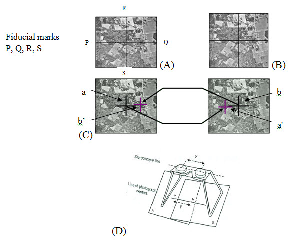
Fig. 8.4. (A), (B) are photographs makes a stereo pair, (C) principal points (a, b) are marked as black and conjugate principal points (a’, b’) are marked as pink. (D) Stereoscope. (Source: www.cof.orst.edu/cof/teach/for220/lecture/Lecture11.ppt, and Girard, 2003)
8.5 Parallax and Altitude Determination
In two successive photos taken in position L1 and L2 separated by a distance equal to the air base B, and the object height is h; a and b are the top and bottom of the object (Fig. 8.5). B is the photo-base i.e. the distance between two successive exposures. For the convenience of the calculation, Figure 8.5 is transferred to Figure 8.6. Point a and b are projected on the joint photograph as xa, xa’ and xb, xb’ correspondingly (Fig. 8.5). The parallax of point a and b are Pa and Pb respectively. To represent this parallax, a pseudo-image is drawn at the focal distance of the camera. The parallax of point a and b is Pa and Pb.
Pa = xa+ xa’ and Pb = xb+ xb’
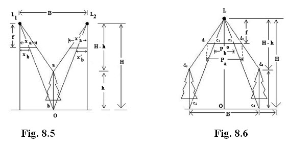
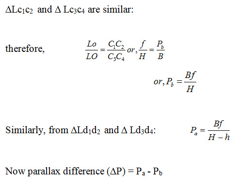
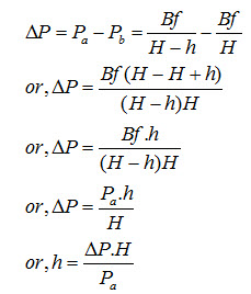
Here, the object height measurement depends on the flight height and parallax of top and bottom of the object.
Keywords: Stereoscopy, Stereoscopic vision, Stereopair, Parallax, Stereoscope.
References
Girard, M., C., Girard, C., M., 2003. Processing of remote sensing data, Mohan Primlani for Oxford & IBH Publishing Co. Pvt. Ltd, pp. 255-276.
www.cof.orst.edu/cof/teach/for220/lecture/Lecture11.ppt
Suggested Reading
Bhatta, B., 2008, Remote sensing and GIS, Oxford University Press, New Delhi, pp. 241-245.
eps.mq.edu.au/courses/GEOS264/maps/mapch3/photo.htm
Lillesand, T. M., Kiefer, R. W., 2002, Remote sensing and image interpretation, Fourth Edition, pp. 148-163.
Last modified: Tuesday, 21 January 2014, 6:19 AM