Site pages
Current course
Participants
General
Module 1: Watershed Management – Problems and Pros...
Module 2: Land Capability and Watershed Based Land...
Module 3: Watershed Characteristics: Physical and ...
Module 4: Hydrologic Data for Watershed Planning
Module 5: Watershed Delineation and Prioritization
Module 6: Water Yield Assessment and Measurement
Module 7: Hydrologic and Hydraulic Design of Water...
Module 8: Soil Erosion and its Control Measures
Module 9: Sediment Yield Estimation/Measurement fr...
Module 10: Rainwater Conservation Technologies and...
Lesson 20 Design of Water Harvesting Structures
20.1 Need for Water Harvesting Structures
Although we generally get a lot of rain in India, we do not have adequate water at all the times and at all the places. The reason for this is the lack of the realization of the value of each rain drop. The average annual rainfall in India is 1,170 mm, which is higher than all the continents except South America as well as the global annual average of around 850 mm. However, the rainfall in India occurs during short spells of high intensity. Because of such high intensities and short durations of heavy rain, most of the rainfall in India tends to flow away rapidly leaving very little amount for groundwater recharge. This results in most parts of India experiencing water scarcity even for domestic uses.
Ironically, Cherrapunji in Meghalaya –historically regarded as the wettest place on earth with a normal annual rainfall of over 11,000 mm, also suffers from acute drinking water shortage. This is because rainwater is not conserved adequately and is allowed to drain away. Thus it does not matter how much rain we get, if we don’t harvest or capture it.
This highlights the need to implement water harvesting through appropriate structures, to ensure that the rain falling over a region is conserved as fully as possible. This can be done by either storing it for direct use on/below/above ground or recharging it into the groundwater.
20.2 Design of Tanks and Ponds for Water Harvesting
Percolation Tank
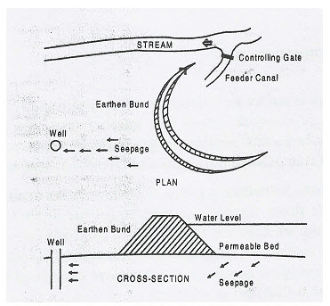
A percolation tank is generally constructed in low level wasteland or a small drain. It has well defined catchment and the water spilling over is diverted to a nearby natural drain. It consists of earthen embankment and an overflow type masonry waste weir. Permeable formation in the reservoir bed is an essential requirement of percolation tank. The tank acts as storage of intercepted runoff, which percolates down to phreatic aquifer creating a recharge mound. The percolation time depends upon the permeability of bed formation. Normally it is expected that between two consecutive rain spells, most of the storage percolates down. Thus, during 2 to 3 rainfall cycles, the actual recharge gain is two to three times the storage capacity of the tank. The shape and size of the recharge mound depends on the nature of phreatic aquifer underlying the surface. This type of recharge structure is useful in area having sandstone and limestone formation underlying [Refer to Fig. 20.1].
Tank is a general term used for surface water storage of moderate size. The storage may have come into being due to interception of rainwater in a natural depression or a manmade excavation. Such water bodies are popularly called ponds. Alternatively water storage may be done by closing the openings of a natural saucer shaped landform by constructing bund sized embankments. The storage so created is called a tank. The tank bunds are mostly constructed with earth to keep cost of construction low and are commensurate with the benefits envisaged.
Water storages of large size are not called tanks, but they are referred to as reservoirs. Such reservoirs are formed in the river valleys by constructing a barrier or a dam using masonry, concrete or earth depending upon site conditions. Technically, bund is a miniature form of a dam.

Fig. 20.1. Schematic Diagram of a Percolation Tank. (Source: Patel and Shah, 2008)
Due to simplicity in construction it was a very popular mode of conserving rainwater. In South India where rivers are monsoon fed, tanks assume special importance. In the plains of Uttar Pradesh, West Bengal and Orissa as also in the plateaus of Madhya Pradesh, Chhattisgarh tanks have been extensively practiced.
Classification of Tanks
Bunds which are generally less than 12 m high, results in tanks. From the consideration of height of bunds, up to 4.5 m high bunds generate a small tank. Medium sized tanks are formed by bunds up to 9 m height. It may however be noted that, this classification is very approximate because the shape and size of the tank is not dependent on the height of the bund alone. It is equally influenced by the topographical features of the region.
Network of Tanks
The tank system may exist with each tank as a separate entity or in the form of a group of tanks in a series or tanks with inter-connection. In a tank system, following types of network exist:
(i) Isolated tanks;
(ii) Tanks with inter-connections; and
(iii) Tanks in series.
Isolated Tanks: When a tank is fed by an independent free draining catchment and also when the surplus flows do not form network inflow into another tank, the tank system is called an isolated tank system. Mostly large and medium sized tanks are constructed as isolated tanks with independent catchment area. Also in the plains and on plateau lands, tanks exist in isolation.
Tanks with Inter-Connections: Sometimes a group of tanks may be so situated that they could be inter-connected to receive flows through, as well as deliver flows to other tanks in the group severally. It thereby implies that the tanks have a combined catchment. Any surplus water received by a tank from the catchment lying above it is transferred to other tanks. Depending upon the prevailing hydro-meteorological conditions, the tanks are capable of feeding either each other or one another. Thus, optimum water utilization and storage is achieved.
Tank in Series: Such tanks are located alongside the river drainage channels. They are fed by inflow drains and serviced by escape or outflow drains. The tanks in upper reaches get their supplies from the catchment through inflowing drains. It then lets its surplus flow down through an escape or outflow drain, which contributes to the inflow of the tank lower down in the series. Thus while the uppermost tanks have substantially free catchment, the tanks lower down have limited free catchment falling between two tanks. The tanks lower down in the series get inflows immediately after rainfall from their free draining catchments. But supplies from already intercepted catchments are received only after the upper tanks get filled. The advantage of this system is that, surplus water from the upper tank is picked up by the lower tanks rather than allowing any wastage.
However, there is a safety related disadvantage. In case of breach in the upper tank, lower tanks also become prone to severe flooding endangering the safety of the tank bunds. To avoid this, breaching sections are provided at appropriate locations in each tank.
Water Harvesting by Ponds
The traditional practice of collection rainwater in village ponds suffers from following limitations:
Large open surface is subjected to high evaporation losses.
Large bed area is subjected to high seepage losses.
In Spite of these limitations in the village ponds, the bulk water requirement for about half the year is met from them. Small groundwater recharge mound formed under the pond bed used to partially supply through wells dug in the pond bed. This traditionally practiced rainwater harvesting structures have served water supply requirements since ages. During the scarcity years, some deepening of ponds is made through de-silting. But if it is done in a haphazard manner, it does not help much and rather it may lead to other problems like water logging, mosquito breeding, etc.
Pond Lining
The limitations of traditional ponds, especially the quality deterioration and seepage losses could be completely stopped by using plastic lining. This simple technique has proved to be effective. The evaporation loss could be checked by use of chemical retardants and adopting system of multiple ponds system (i.e., compartments). Limitation of the depth factor has to be accepted and required storage could be built by increasing the length and breadth of the pond. Of course, in places where salty water is available is at greater depths, the pond storage can be increased even with less open surface and thereby reducing the evaporation losses. Such favorable locations may not be provided with plastic lining, provided the rate of salt contamination from the sediments is within the limits. Plastic lining is a rather costly proposition, however, it envisages better use of local water resources and regular maintenance is almost negligible.
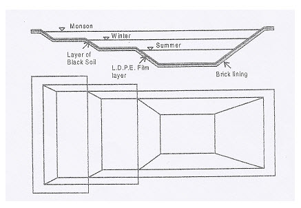
This technology involves lining of the walls and floor of the pond, tank reservoir with tough, wide-width low-density polyethylene (LDPE) film. These LDPE films are available in widths of 4 to 12 m and thickness of 100 to 250 microns. These films meet specifications as per the Bureau of Indian Standards Code IS: 2508 - 1984. This film has excellent water barrier properties, very good blend of physical properties such as tensile impact strength coupled with good weathering capability and chemical resistance properties. These films also prevent the inherent salinity of the soils and saline groundwater from seeping into the pond or tank and start contamination.
The construction of plastic lined pond includes excavation work, screening work for removing big boulders and sharp edged gravels which could damage the plastic film, dressing of sides and beds so that lining is not punctured, laying plastic film on beds and sides, brick lining on the sidewalls, soil filling on the floor, inlet system and distribution system. By 2008, 19 villages of Bhal area of Gujarat, India had 20 such plastic lined ponds [Refer to Fig. 20.2].

Fig. 20.2. Water Harvesting by Plastic Lined Ponds. (Source: Patel and Shah, 2008)
Keywords: Water harvesting structures, Percolation tank, Tank networks, Water harvesting by ponds, Plastic lined water ponds.
References
Agarwal, A. and Narain, S. (2000). A Water Harvesting Manual, Centre for Science and Environment.
Centre for Science and Environment, (2000). A Water Harvesting Manual for Urban Areas, pp. 3, Centre for Science and Environment.
Patel, A. S. and Shah, D. L. (2008). Water Management, New Age International Publishers, pp. 106-107, 122-124.
Suggested Reading
Agarwal, A. and Narain, S. (1997). Dying Wisdom, State of India’s Environment 4, Centre for Science and Environment.
Agarwal, A., Narain, S. and Khurana, I. (2001). Making Water Everybody’s Business, Centre for Science and Environment.