Site pages
Current course
Participants
General
Module 1. Classification of Farm Power Sources
Module 2. Classification of IC Engines & Therm...
Module 3. Performance Characteristics
Module 4. Engine Components
Module 5. Engine Operating System
Module 6.:Engine Fuel System
Module 7. Engine Governor
Module 8. Engine Cooling & Lubrication system
Module 9. Engine Ignition System
26 April - 2 May
LESSON 16. Fuel Injection Pump & Nozzles
16.1 Fuel Delivery & Injection
It involves the flow of fuel from fuel tank to fuel nozzles for injecting the desired quantity of fuel with required pressure in the combustion chamber. Fuel travels fuel pipes from fuel tank to fuel feed pump through primary filter under gravity and then with the help of fuel injection pump, it further reaches to injecting nozzles with pressure through high pressure pipes. Engine speed tends to overshoot to hazardous values on reduction of load and also to very low speed (almost on the stage of engine halt) on increase in sudden and unexpected load application. To avoid such conditions, the engine speed is controlled by regulating the fuel supply by using engine governor which has been discussed in detail in lecture no. 22 & 23.
16.2 Fuel feed pump
The fuel comes from the fuel tank to the fuel feed pump which makes it to reach fuel injection pump after traveling through primar
y and secondary fuel filters. Sometimes this feed pump is also known as transfer pump or lift pump. Various types of feed pumps are used for the engines depending upon the application for which they are to be used. Fuel feed pumps can be of following types.
- Diaphragm type
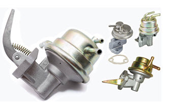
- Gear type
- Vane type
- Plunger type
The hand priming pump is meant to bleed the fuel supply system when required. If the engine has not been working for a considerable period, the fuel can be transferred rapidly from the fuel tank to the fuel injection by hand-priming pump.
16.3 Fuel injection
The fuel injection system is required to inject the atomized fuel coming from fuel injection pump at high pressure to inject into cylinders/combustion chamber in exact and desired amount of fuel at desired time. Usually solid injection system is the most common system being used these days for injecting the liquid fuel which has been further classified into following two types.
- Common rail fuel injection system
- Individual pump fuel injection system.
16.3.1 Common rail fuel injection system
Common rail fuel injection system has single injection pump with individual injector which is also known as unit injector on each cylinder injector. These individual injectors are operated by rocker arms and springs connected with control racks through the linkage to control the fuel injection in all cylinders simultaneously.
16.3.2 Individual pump fuel injection system
Plunger type or the diaphragm type in-line fuel feed pumps are used to inject fuel in the cylinders. The fuel travels from fuel tank with the help of fuel feed pump being driven by injection pump camshaft. Hand-priming lever is provided in the fuel feed pump to initiate the fuel flow and also to blow the air out from pump. The fuel then travels through filters and injection pump to reach engine cylinders in the desired quantity according to the firing order.
16.4 Fuel injection pump

The fuel injection pump is used to deliver an accurate and metered quantity of fuel under high pressure, at the correct instant and in the correct sequence, to the injector fitted on each engine cylinder. The injection pressures generally varies in the range from 7 to 30 MP and can be exceptional high as 200 MPa. The fuel injection pump is driven by timing gears and is controlled by the operator through hand or foot accelerator in a tractor. These fuel injection pumps are designed and manufactured with high precision as these are used for metering very low volume of fuel and very high frequency of injection
The fuel injection pumps are generally of jerk pump type. However, in many cases, distributor type pumps are also used. Both of these will be discussed here.
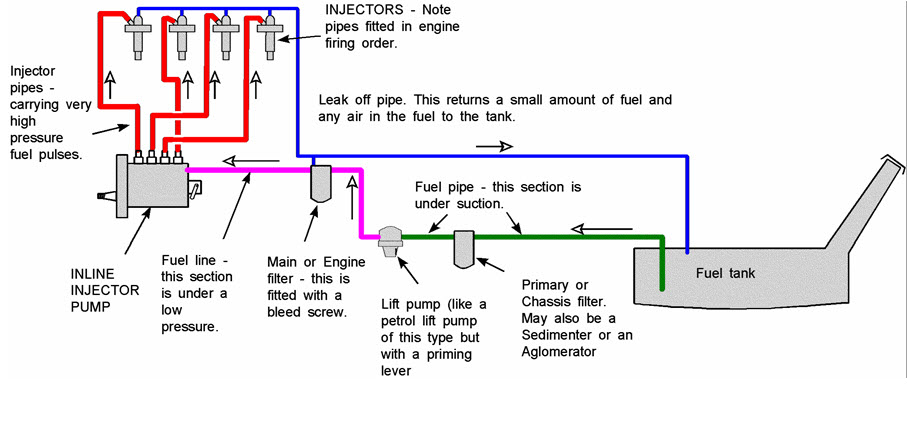
16.4.1 Inline type fuel injection pump
Inline type fuel injection pumps are also known as jerk type fuel pumps. These can be used for both single cylinder and multi-cylinder engines. Mainly it consists of spring loaded delivery valve, the plunger, the control sleeve and the control rack. The plunger contains a helix at its upper end which is operated by cam and tappet to controls the quantity of fuel to be injected.
In multi-cylinder engines, multiple pump assemblies, one for each cylinder, are assembled into one unit to give a compact construction. Fuel comes out from the injection pump with such a high pressure that specially designed and manufactured high pressure delivery lines are used to transfer this pressurized fuel to different fuel injectors mounted on each cylinders. In-line pumps are consist of pump housing, governor housing, camshaft-tappet assemblies and the pumping elements. The function of the camshaft is to generate plunger movement for each pump in the prescribed firing order and at the correct instant. The pump housing is made of aluminum alloy casting which contains camshaft-tappet assemblies, control mechanism and governor and the pumping head.
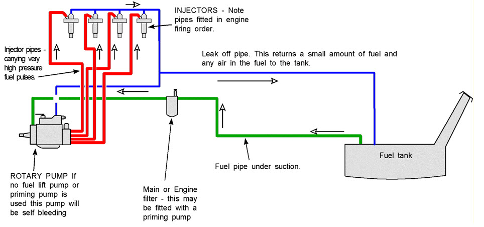
16.4.2 Rotary type fuel injection pump
These rotary type fuel injection pumps are also known as distributor pumps in which the fuel is distributed to each cylinder by means of a rotor. The rotor has a set of radial holes (suction and delivery ports) equal to the number of engine cylinders. Each of the delivery ports is connected to the high pressure delivery lines leading to injectors mounted on the each cylinder in multi-cylinder engines. As the rotor revolves, the suction ports align with the intake metering port one by one, while the distribution port aligns with the delivery ports in turn. Internal cam ring is used to control the fuel injection timing in these rotary pumps. With the increase in engine speed, the fuel feed pump delivery pressure increases which moves the cam in an advance direction to provide more timing. Rotary fuel injection pumps are compact, small in size and have less weight. Since there is a single rotor being used for delivering fuels to the multiple cylinders through individual high pressure pipes, the equal quantity of fuel is delivered which helps in even combustion of fuel in all the cylinders as per the firing order and generating consistent power strokes.
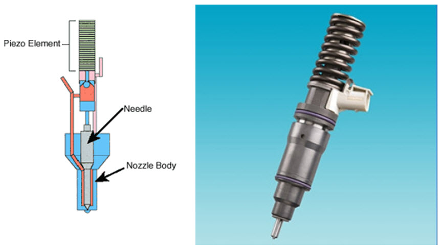
16.5 Fuel nozzles
These are also known as injectors, atomizers or fuel valves. Nozzles are used to inject the fuel in the combustion chamber/cylinder in a desired atomized form and in exact quantity on exact time. Generally, replaceable nozzles are provided with screw caps to ease the change of nozzle whenever required. A spring-loaded spindle is used to keep the nozzle valve pressed against its seat in the nozzle body. As the fuel is supplied by fuel injection pump with sufficient pressure to lift the nozzle valve against the spring force, then a spray of atomized fuel is fed into the combustion chamber. The fuel spray continues till the nozzle valve closes back on its seat. The pressure at which the nozzle valve opens is adjusted by a screw provided at the top of nozzle. Following are the two types of nozzles being used in engines these days.
- Hole type nozzles
- Pintle type nozzles
Hole type nozzles are the most commonly used in engines having open type combustion chambers, whereas pintle type nozzles are common in engines with pre-combustion chambers and some special swirl chambers. The pintle type nozzles carry an extension, which produces a hollow cone type spray. Such nozzles have the advantage of being self-cleaning. The opening pressure of hole type nozzles varies from 17 to 34 MPa, whereas that of pintle type nozzles varies from 7 to 15 MPa.
Last modified: Wednesday, 29 January 2014, 5:30 AM