Site pages
Current course
Participants
General
MODULE 1.
MODULE 2.
MODULE 3.
MODULE 4.
MODULE 5.
MODULE 6.
MODULE 7.
MODULE 8.
MODULE 9.
MODULE 10.
LESSON 18 LEAF SPRINGS
18.1 Introduction
A cantilever beam or a simply supported beam can be used as a spring. For example diving board used in a swimming pool is a spring in the form of a cantilever beam. Such springs are called leaf springs. Basic equations of beam can be used to find stress and deflection in the leaf springs.
Let us consider a flat plate with width ‘B’, thickness ‘t’ and length ‘l’. If this plate is used as a leaf spring in the form of a cantilever, subjected to load ‘F’, as shown in figure 18.1, maximum stress and deflection in the plate is given by:
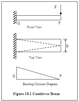
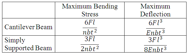
As the bending moment varies linearly along the length of the plate as shown by the bending moment diagram, maximum value of bending stress occurs at the point of support of the cantilever (Q) and it decreases linearly as we move away from the point of support and is zero at the point P. Material can be saved if the cross-sectional area is reduced from Q to P in such a way that each section has same binding stress. Beam so formed is called beam of uniform strength.
Cross-section can be reduced linearly by reducing either the width or thickness. Generally the thickness is kept constant and width ‘B’ is reduced as shown by dotted lines in the top view of plate shown in figure 18.1. If we consider only binding stress, we can have zero width (B = 0) at point P. But practically we cannot have zero width and also at each point in the beam the cross section must be enough to resist the shear force, which also exists in addition to bending. So we need to have some minimum value of B at point P also. Beam of uniform strength so formed has the same value of maximum binding stress as that in case of beam of uniform cross-section but maximum deflection increases. Higher deflection means that they have more resistance and capacity to absorb impact energy and can store more energy in comparison to the spring of uniform cross-section with same value of maximum binding stress.
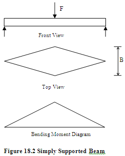
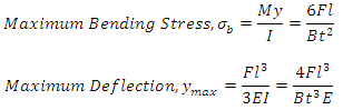
In a similar way simply supported a beam of uniform cross-section and uniform strength can be compared. Figure 18.2 shows simply supported beam of uniform strength. Comparison of stress and maximum deflection is given in table 18.1.
Table 18.1 Stress & Deflection in Beams of Uniform Cross-section & Uniform Strength
18.2 Laminated Springs
The width ‘B’ may become too large if only a single leaf spring is used. In order to make the spring compact, the original plate may be cut into a number of strips which can be placed one below the other and assembled using a clamp as shown in figure 18.3.
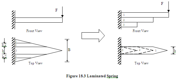
If friction between the strips (also called leaves) is neglected, stress and deflection equations used for original plate can be used for this arrangement by replacing ‘B’ with ‘nb’, where n is number of strips or leaves and b is width of each strip. Relation of maximum bending stress and maximum deflection of cantilever beam and simply supported beam of uniform strength, in the form of a laminated spring, are given in table 18.2.
Table 18.2 Stress & Deflection in Beams Used as Laminated Springs
Laminated springs are used in automobile suspension, railway carriages, coaches etc.
18.3 Semi-elliptical Laminated Springs
Semi-elliptical leaf spring is the most popular and widely used leaf spring. It consists of a number of flat plates or leaves of semi-elliptical shape. U-bolts and center clip are used to hold these leaves together. To keep the leaves aligned and avoid lateral shifting, rebound clips are used. Ends of the longest leaf are bent to form eyes. This longest leaf is called ‘master leaf’ and other smaller leaves are called ‘graduated leaves’. One or two extra full length leaves are generally provided along with the master leaf, to increase strength against the transverse shear force. Typical semi-elliptical leaf spring is shown in figure 18.4.
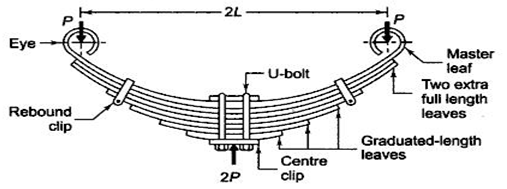
Figure 18.4 Semi-elliptical Leaf Spring
When no external load is acting, the spring is curved or cambered. Camber is the perpendicular distance between the reference line and the master leaf and its magnitude is such that the spring is approximately straight under the max static load. Center of the spring is fixed to the axle of the automobile.
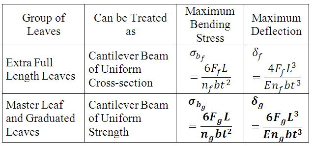
For the analysis purpose, leaves are divided into two groups: i. Master leaf and graduated leaves ii. Extra full length leaves. Let
ng = number of graduated-length leaves including master leaf
nf = number of extra full length leaves
n = total number of leaves
b = width of each leaf
t = thickness of each leaf
L = half the length of semi-elliptical spring
F = force applied at the ends of the spring
Ff = part of F taken by extra full length leaves
Fg = part of F taken by graduated leaves and master leaf
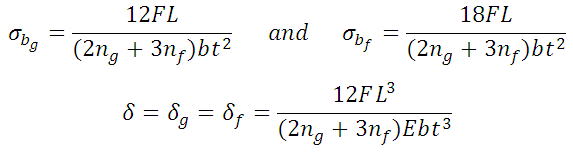
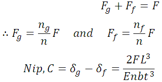
Now, this spring can be treated as a simply supported beam of length 2L, with load 2F acting at its centre or for simplification of analysis, half portion of it can be considered as a cantilever of length L, with one end fixed (centre of the spring which is fixed with axle) and load F acting on the other. Now the first group of leaves i.e. master leaf along with the graduated leaves can be considered as a cantilever beam of uniform strength as discussed in previous article. Similarly group of extra full length leaves can be considered as a cantilever beam of uniform cross-section. Therefore the relations given in table 18.1 can be used to write the stress and deflections in these leaves by replacing B with ‘nf b’ and ‘ng b’ and considering the the share of load taken by them, as given in table 18.3 below.
Table 18.3 Stress & Deflection in Leaves of Semi-elliptical Leaf Spring
As deflection in the full length leaves and graduated leaves is equal,
Also, 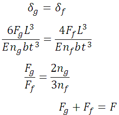
Solving,
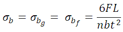
Final relation for stress and deflection can be written as,
18.4 Nipping of Leaf Springs
It is clear from the above equations that the stress in the full length leaves is 50% higher then the graduated leaves. In addition to this, the full length leaves als
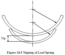
o have to carry transverse load, longitudinal load and also the load due to twisting, which further increases the stress in the full length leaves. In order to reduce the value of maximum stress in the full length leaves and to equalize the stresses in different leaves the spring may be pre-stressed in such a way that the full length leaves are stressed in the opposite direction to the stresses due to external load. This is done by giving different radius of curvature to the full length leaves than the graduated leaves. Full length leaf is given higher radius of curvature than the adjacent leaf and it is reduced further for smaller length leaves. Initial gap between the full length leaf and graduated leaf is called nip and this process is known as nipping. The leaves get pre-stressed when they are clamped together. As discussed earlier, pre-stressing leads to equalization of stresses in graduated leaves and full length leaves, therefore
Also, 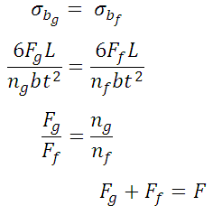
Initial pre-load required to close the gap C can be determined as follows:
Nip is equal to the sum of initial deflections in the full length leaves and graduated leaves,
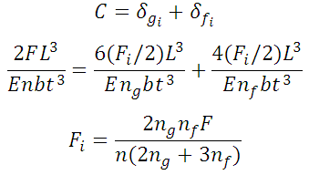
Resultant stress in the extra full length leaves is then given by,
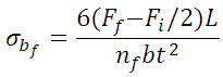
Substituting the values of Ff and Fi
And considering that the stress in all the leaves should now be equal,
References
-
Design of Machine Elements by VB Bhandari
-
Mechanical Engineering Design by J.E. Shigley
-
Analysis and Design of Machine Elements by V.K. Jadon
-
Machine Design by R.S. Khurmi
-
Design of Machine Elements by C.S. Sharma & K. Purohit
Last modified: Friday, 21 March 2014, 4:57 AM