Site pages
Current course
Participants
General
MODULE 1.
MODULE 2.
MODULE 3.
MODULE 4.
MODULE 5.
MODULE 6.
MODULE 7.
MODULE 8.
MODULE 9.
MODULE 10.
LESSON 23 DESIGN OF SPUR GEARS
23.1 Force Analysis
To transmit power from one gear to the other, force is applied by the tooth of the driving gear on the mating tooth of the driven gear. This force, called as Normal Force ( ) acts along the pressure line and is always normal to the tooth surface. This normal force can be resolved into two components:
- Tangential component (Ft)– helps in transmission of torque and determines its magnitude.
- Radial component (Fr)– tends to push the gears apart, has no contribution in power transmission.
If torque to be transmitted, T is known, tangential component of force can be calculated as,

Where d is pitch circle diameter
Fn acts along the pressure line and Fn along the common tangent, therefore angle between Fn and Ft is φ , the pressure angle. Referring to Figure 23.1, following relations can be written:
Fr =Ft tan φ and Fn = Ft/cos φ
Above analysis is based on the following assumptions:
-
Fn remains constant in the power transmission (Fn changes with change in position of the point of contact).
-
Only one pair of teeth takes the entire load (Load is often shared by more than on pairs).
-
Loads are static i.e. gears run at a low speed (There are dynamic loads in actual practice).

Figure 23.1 Normal Force Resolved into Tangential & Radial Components
23.2 Gear Material
As for any other component, selection of material depends upon performance requirements, material properties, manufacturing aspects & cost and availability. Gear material should have good strength, high endurance limit, good wear resistance, low coefficient of friction and good manufacturability. Gears are subjected to dynamic loads and very high bending and contact stresses.
Cast iron can be used for lighter stress conditions. It has good castability, machinability and wear properties. Also its vibration damping property makes the operation quiter. For light to medium duty gears steel castings and structural steels may be used. Hardened and tempered steel or case-hardened steels are used for heavy duty applications. For working conditions where special properties, like resistance to heat, corrosion or wear, are desired, alloy steels can be used bronzes, aluminium and zinc alloys are some other material that are used for manufacturing gears, due to their high strength and good sliding properties. Non-metallic materials like acetal, nylon and other plastics are also used for manufacturing gears. These are quieter, durable, cheaper and don’t require lubrication also but their bad carrying capacity is low. Gears can be manufactured with the help of casting, forging or machining.
23.3 Gear Tooth Failure
Gear tooth may fail in two ways – breakage of tooth due to overloading or fatigue or Surface damage of the tooth due to wear, pitting or scoring. These are discussed below:
23.3.1. Breakage of Tooth
Each tooth of gear is subjected to bending stress, which is maximum at the fillet of its base. Gear tooth may fail, if this stress reaches the yield strength of the material. Also as the load on the tooth is dynamic in nature, it leads to variable stresses and the tooth may fail due to fatigue.
23.3.2. Surface Damage of the Tooth
Surface of gear tooth is subjected to very high contact stresses at the point of contact between two mating gears, where the normal force acts. Surface of the tooth may get damaged due to these very high contact stresses. Gear-tooth surface damage is a very complex phenomenon as excessive loading and lubrication breakdown may lead to various combinations of abrasion, pitting, and scoring. These three basic types of surface deterioration are briefly discussed below:
Abrasion (Abrasive wear) is a type of wear caused by the presence of foreign particles on the surfaces of contact between two mating gears. These foreign particles may be present at the time of assembly or may enter along with the lubrication oil if it is not filtered properly.
Scoring is a form of adhesive wear, which is generally caused due to the failure of lubrication film between the two surfaces i.e. due to inadequate lubrication and occurs in gears rotating at very high speeds. Inadequate lubrication leads to increase in coefficient of sliding friction that combines with high sliding velocity and very high tooth loads to produce a high rate of localized heat generation. This high temperatures and pressure condition causes welding and tearing apart of the tooth surface, which is called scoring. It can be prevented by providing good surface finish and using an appropriate lubricant.
Pitting and Spalling are types of surface fatigue failures that are characterized by the separation of small bits of material from the surface of the tooth. Due to very high localized stresses, cracks are initiated on and under the contacting surfaces of the teeth, which start propagating, finally resulting in loss of material from the surface in the form of bits. If this phenomenon starts with surface cracks resulting in pits of relatively smaller size, it is called pitting. And if it originates with subsurface cracks resulting in thin flakes of surface material, it is called Spalling.
23.4 Beam Strength of Gear Tooth
Wilfred Lewis presented first recognized analysis of bending stress in gear tooth in 1892, which serves as the basis of bending stress analysis of gear teeth, even today. Lewis considered the gear tooth as a cantilever beam, subjected to bending moment due the tangential force acting on it, as shown in Figure 23.2.

|
Figure 23.1 Gear Tooth as Cantilever |
Lewis Analysis is based on following assumptions:
-
Only one pair of teeth takes the entire load (Load is often shared by more than on pairs).
-
The effect of radial component, Fr, is negligible (Fr induces compressive stress).
- The load is uniformly distributed across the full face width. (Gear should be rigid and accurately machined for this).
- Tooth sliding friction forces are negligible.
- Effect of stress concentration is negligible.
Cross-section of the gear tooth, considered as a cantilever beam, varies from the free end to the fixed end. A parabola can be constructed within the tooth profile, as shown in Figure 23.1, giving the outline of a beam of uniform strength. Cross-section at XX is critical, where this parabola is tangent to the tooth profile. If b, t and h are width, thickness and height of the gear tooth, Bending Stress at section XX can be given by,
![]()
Multiplying nominator and denominator by ‘m’ and rearranging,
![]()
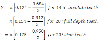
where Y = t2 / 6hm = Lewis Form Factor
Above equation gives the relation between tangential force and bending stress in the tooth. increases with increase in . The maximum tangential load that can be transmitted by the tooth without bending failure is called its Beam Strength . Therefore in the above relation, if is replaced by allowable bending stress, of the tooth, corresponding value of is the beam strength.
![]()
Value of for different systems can be taken as given below:
For the gears to be safe in bending,σb should be less than [σb] or Ft should be less than Sb . If gear and pinion are made of same material, pinion is the weaker member and design is based on its strength. But if those are made of different materials, it is evident from the Lewis Equation that the gear or pinion having lesser value of product [σb] X Y is weaker, as m and b are same for pinion and gear. Also as the gears are subjected to variable stresses, design is based on the endurance limit and allowable bending stress can be taken as, [σb] = Se/fos
References
-
Design of Machine Elements by VB Bhandari
-
Mechanical Engineering Design by J.E. Shigley
-
Analysis and Design of Machine Elements by V.K. Jadon
-
Fundamentals of Machine Component Design by R.C. Juvinall & K.M. Marshek
-
Design of Machine Elements by C.S. Sharma & K. Purohit
-
Machine Design by R.S. Khurmi
-
Mechanical Design by Peter Childs
-
Machine Design by PC Sharma & DK Aggarwal
Last modified: Friday, 21 March 2014, 10:03 AM