Site pages
Current course
Participants
General
MODULE 1.
MODULE 2.
MODULE 3.
MODULE 4.
MODULE 5.
MODULE 6.
MODULE 7.
MODULE 8.
MODULE 9.
MODULE 10.
LESSON 24 DESIGN OF SPUR GEARS-II
24.1 Effective Load on the Gear Tooth
As discussed above, is calculated for rated torque and rated speed, and therefore is average value of the tangential force on the tooth. But in actual conditions, torque developed by the power source and also the torque requirements of the driven machinery vary. To account for these variations in service conditions, Ft is multiplied with Service Factor (Cs). Also, Ft was calculated assuming that gears are rotating at a very slow speed, which is generally not the case. Gears rotate at appreciable speeds resulting in dynamic forces, which may occur due to inaccuracies in tooth profile, misaligned bearings, inertia and elasticity of the members. To account for the effect of this dynamic force, Velocity Factor (Cv) is used. Effective Tangential Force acting on the tooth is then given by, ![]()
Values of and can be taken from the table 24.1 and table 24.2 respectively.
Table 24.1 Service Factor,
|
Power Source |
Driven Machinery |
||
|
Uniform |
Moderate Shock |
Heavy Shock |
|
|
Uniform |
1.00 |
1.25 |
1.75 |
|
Light Shock |
1.25 |
1.50 |
2.00 |
|
Medium Shock |
1.50 |
1.75 |
2.25 |
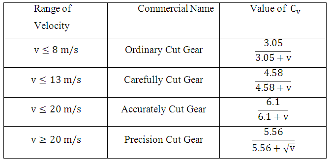
Table 24.2 Barth’s Formulae for Velocity Factor,
Therefore for the gear tooth to be safe,Feff should be less than Sb.
Above calculation of Feff gives approximate estimation of the effective tangential force acting on the gear tooth and can be used in the initial stages of design. For more accurate calculation, Buckingham’s equation is used, which takes into account inertia of connected masses, elasticity of gear material, tooth profile inaccuracies etc. All these important aspects are neglected in previous method as the velocity factor depends only on the pitch line velocity of gears. According to Buckingham, effective tangential load on the gear tooth is given by,
![]()
where, Fd is the additional load due to dynamic conditions, called as ‘Incremental Dynamic Load’ and is given by,
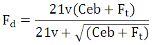
where, v = pitch line velocity (m/s)
e = sum of errors between two meshing teeth (mm)
b = face width of the tooth (mm)
C = Deformation Factor (N/mm2), which is given by,
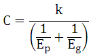
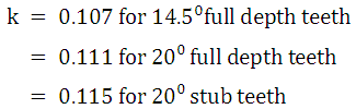
where, and are Modulii of Elasticity of pinion and gear respectively and is a constant that depends upon the form of the tooth. Value of can be taken as given below:
Error e depends upon method of manufacturing and quality of gear. There are twelve grades from Grade 1 to Grade 12, in decreasing order of precision. Standard tables giving tolerances for these grades are available and error is expected to be equal to those.
24.2 Wear Strength of Gear Tooth
Wear Strength is the maximum value of tangential load that the tooth can transmit without surface damage. It can be calculated using the Buckingham’s Equation as given below:
![]()
where,
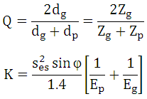
Where is Surface Endurance Limit, which is related to Brinell Hardness Number as:
![]()
24.3 Design Procedure for Spur Gear
1.Select suitable material and design stress.
![]()
2.Assume number of teeth on pinion (Zp), considering minimum teeth required to avoid interference.
3.Calculate and identify weaker of pinion and gear.
4.Select suitable value of service factor Cs,
5.Assume / calculate values of and Cv.
K is the ratio of face width to module and is known as face width ratio i.e. k = b / m . Value of lies between 9.5 and 12.5 and is generally assumed to be 10.
For Cv, if the centre distance between the gears is known, pitch line velocity (v) can be calculated and , corresponding to that can be calculated using Barth’s formula given in table 24.2.
Therefore, if centre distance is unknown, assume and for known centre distance (CD) following steps can be followed:
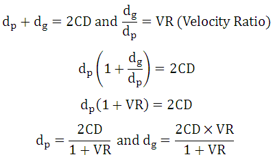
Thus pitch circle diameter of pinion or gear can be calculated for known centre distance and desired velocity ratio and can then be calculated.
6. Calculation of Module
For the gear tooth to be safe in bending, ![]() and to calculate limiting value of module,
and to calculate limiting value of module,
![]()
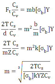
Value of module can be estimated using this relation and closest standard value of module is selected.
7. If centre distance is unknown, calculate d = mZ, calculate ![]() and recalculate . And for known centre distance, calculate Z = d / m and recalculate Y and m .
and recalculate . And for known centre distance, calculate Z = d / m and recalculate Y and m .
Repeat steps 6 and 7 until two consecutive values of module are found to be same.
8. Check the design for bending using Buckingham’s equation. Calculate Fd & Feff and compare it with Sb. If design is no safe higher values of standard module can be checked.
9. Check the design for wear strength using Buckingham’s equation. Feff should be ≤ Sw. If not, increase in surface hardness may be recommended.
References
- Design of Machine Elements by VB Bhandari
- Mechanical Engineering Design by J.E. Shigley
- Analysis and Design of Machine Elements by V.K. Jadon
- Fundamentals of Machine Component Design by R.C. Juvinall & K.M. Marshek
- Design of Machine Elements by C.S. Sharma & K. Purohit
- Machine Design by R.S. Khurmi
- Mechanical Design by Peter Childs
- Machine Design by PC Sharma & DK Aggarwal
Last modified: Monday, 24 March 2014, 4:20 AM