Site pages
Current course
Participants
General
Module 1. Introduction about design and developmen...
Module 2. Study of special design features of trac...
Module 3. Study of basic design parameters for tra...
Module 4. Selection of different mechanical power ...
Module 5. Study of tractor steering and suspension...
Module 6. Design and analysis of tractor hitch sys...
Module 7. Design of a tractor hydraulic system
Module 8. Study of electrical, electronics and gui...
Module 9. Ergonomics, controls and safety features...
Module 10. Tractor testing
Lesson 11. Different types of gear and power transmission systems in tractors.
1. Introduction
Transmission is a speed reduction mechanism, equipped with several gears. The simplest transmissions, often called gearboxes, provide gear reduction sometimes in conjunction with a right-angle change in direction of the shaft. It may be called a sequence of gears and shafts, through, which the engine power is transmitted to the tractor wheels. These are often used on PTO-powered agricultural equipments. The complete path of power from the engine to the wheels is called power train (Fig. 11.1)
The purpose of transmission is to reduce the engine speed and increase the torque available at the rear wheels of the tractor because
HP = T.N
Where,
T is torque (kg-m) and N is rev/min.
If the engine hp is constant, it is obvious that for higher torque at wheels, low speed is required and vice-versa. So the gear box is fitted between engine and rear wheel for variable torque and speed. This is done by suitable design of gear and shafts.
The transmission uses gears to make more effective use of the engine and keeps the engine operating at an appropriate speed. Transmission's primary job is to allow engine to operate in four or five different speeds. Today's four- and five-speed automatic transmissions need torque converters with coolant, radiators and hoses — all of which cause loss of power and efficiency.
Speed varies according to the field requirements and so a number of gear ratios are provided to suit the varying conditions.
I. Function of transmission system:
To transmit power from the engine to the rear wheels of the tractor.
To make reduced speed available, to rear wheels of the tractor.
To alter the ratio of wheel speed and engine speed in order to suit be field conditions.
To transmit power through right angle drive, because the crankshaft and rear axle are normally at right angles to each other.
II. Transmission Gears
A gear is a toothed wheel designed to transmit torque to another gear or toothed component. The teeth (or cogs) of a gear are shaped to minimize wear, vibration and noise, and to maximize the efficiency of power transmission.
Different-sized gears are often used in pairs for a mechanical advantage, allowing the torque of the driving gear to produce a larger torque in the driven gear at lower speed, or a smaller torque at higher speed. The larger gear is known as a wheel and the smaller as a pinion. This is the principle of the automobile transmission, allowing selection between various mechanical advantages. A gearbox is not an amplifier or a servomechanism. Conservation of energy requires that the amount of power delivered by the output gear or shaft will never exceed the power applied to the input gear, regardless of the gear ratio. There is actually some loss of output power due to friction.
III. Types of gear:
a) Spur gears:
These are Flat with teeth projecting radially in the plane of the wheel, "straight-cut gears". These gears can be fitted only to parallel axles (Fig. 11.2).


Fig. 11.2: Spur gear
(Source: http://www.micro-machine-shop.com/gear_nomenclature_1.jpg)
(http://www.wmberg.com/images/gear.gif)
a. Spur gear design
1) Gear tooth loads
The load on the gear tooth is given by
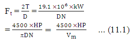
Where, T = torque transmitted, N-m
D = pitch diameter, mm or m
N = RPM of gear or shaft
Vm= pitch line velocity, mpm
2) Bending strength of gear tooth
The bending strength (σ) of gear tooth is given by
![]()
Sector gear is merely a segment of a spur gear, such as one half or one quarter of the circumference, but still attached to the axle in the normal fashion. Rack and pinion allows torque to be converted to linear force. The pinion is a spur gear, and mates with a toothed bar or rod that can be thought of as a spur gear with an infinitely large radius of curvature. Such a mechanism is used in automobiles to convert the rotation of the steering wheel into the left-to-right motion of the tie rod(s).
b) Helical gears:
A refinement over spur gears (Fig. 11.3). The teeth are cut at an angle, allowing for more gradual, hence smoother meshing between gear wheels, eliminating the whine characteristic of straight-cut gears. - Double helical gears - Also known as herringbone gears. These gears have teeth that are 'V' shaped. Each gear in a double helical gear can be thought of as two standard, but mirror image, helical gears stacked. This cancels out the thrust since each half of the gear thrusts in the opposite direction. They can be directly interchanged with spur gears without any need for different bearings.

Fig. 11.3: Helical gear
(Source:http://www.flohmueller.de/pov_anim/engineering/Cog_Wheel_Helical22_5_100_50c.gif)
b. Design of Helical Gears
The forces acting on helical gear
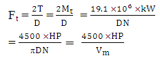
1) Tangential Force (Ft)
The tangential force (Ft) is given by
2) Separating Force (Fr)
The separating force (Fr) is given by
Fr = Ft tan Φ
Thrust Force (Fa)
The thrust force (Fa) is given by
Fa = Ft tan α
Where, ϕ = Pressure angle measured in a plane perpendicular to the axis of gear
α = Helix angle measured from the axis of gear
Worm gears is gear that resembles a screw, with parallel helical teeth, and mates with a normal spur gear. The worm gear can achieve a higher gear ratio than spur gears of a comparable size.
c) Bevel gears:
These gears allow to change the operating angle. However one wheel of such gear is designed to work with it's complementary wheel and no other (Fig. 11.4). Four bevel gears in a square make a differential gear, which can transmit power to two axles spinning at different speeds, such as those on a cornering automobile.

Fig. 11.4 Bevel gear
(Source: http://hgp.hdsb.ca/Grade4/FOV1-000C664C/S08AB36D9.4/bevel%2520gear.gif)
c. Design of bevel gears
1) Forces in bevel gears
 ... (11.3)
2) Axial Force (Fn)
![]() ... (11.4)
... (11.4)
3) Radial Force (FR)
![]() ... (11.5)
... (11.5)
Where, ϕ = Angle between F tm and Fn, and
δ = Cone angle of bevel gears.
d) Planetary gear unit
The details of planetary gear unit shown in Fig. 11.5.
Gear ratios of planetary sets:
(i) Planet stationary sun rotating
![]() ...(11.6)
...(11.6)
(ii) Ring stationary sun rotating
![]() ... (11.7)
... (11.7)
(iii) Sun stationary ring rotating
![]() ... (11.8)
... (11.8)


Fig. 11.5 Planetary gear unit
(Source:http://www.beam-wiki.org/w/images/1/16/Epicyclical(Planetary)_Gear_Train.GIF)
(http://www.hhbearing.com/images/Planetary_Gears.gif)
Crown gear is a special form of bevel gear which has teeth at right angles to the plane of the wheel; it meshes with a straight cut spur gear or pinion on a right-angled axis to its own, or with an escapement such as found in mechanical clocks
IV. Tractor Transmission Types
Tractors are to be used for heavy field works especially tillage operations that require maximum tractive power and P.T.O work where correct P.T.O speed is essential. At rated engine speed of tractor correct P.T.O speed should be available for getting maximum P.T.O power from the tractor. Most of the field operations for crop cultivation need forward speeds between 3-6 km/hr. Therefore, selection of suitable speed ratios in this range for different types of field works is of vital importance. In tractor the rear drive wheels require power at lower speed and high torque whereas its engine runs at higher speed and low torque. Therefore, the purpose of gearbox transmission is to provide speed reduction and multiply the torque received from the engine. Main principle of gear train transmission is given by the following relationship.
![]() ... (11.9)
... (11.9)
Where,
Ndriver (N1) = speed of driving gear, rpm
Ndriver (N2) = speed of driven gear, rpm
Tdriver (T1) = number of teeth in driving gear
Tdriver (T1) = number of teeth in driven gear
i. Transmission Systems:
Most common type of power transmission used in tractors are as under:
a) Manual Transmission
Sliding gear
Constant mesh
Synchronized or Synchromesh
Power shift
b) Automatic Transmission
c) Hydrostatic
d) Hydro-dynamic
a) Manual Transmission
A manual transmission is a type of transmission used in automotive applications. Manual transmissions often feature a driver-operated clutch and a movable gear selector, although some do not. If you have a manual transmission, you have to shift the gears yourself, usually with a stick located on your console and the clutch pedal. Manual transmissions are characterized by gear ratios that are selectable by engaging pairs of gears inside the transmission. Manual transmissions are generally available with four to six forward gears and one reverse gear, although manual transmissions have been built with as few as 2 and as many as 7 gears. Some manuals are referred to by the number of forward gears they offer (e.g., 5-speed) as a way of distinguishing between automatic or other available manual transmissions. Manual shift transmissions, while not as user-friendly as some of the other types, tend to have cast iron durability. It has no synchronizers thus one have to stop and clutch for each gear change. One can’t shift on the go without grinding gears. Its usually have 6-8 forward gears and 1-2 reverses.
Manual transmissions are of these types:
It is the plain old standard shift transmission. The two most popular styles of manual shift transmissions are the sliding gear, and the collar shift. In the sliding gear style, the gears are splined to the main shaft, and gear selection is made by actually moving the gears, via shift forks, into the appropriate location.
a) Sliding gear transmission:
Basic gear type transmission is sliding gear transmission (Fig. 11.5). Consists of input shaft and output shaft parallel to each other inside housing or case. Third shaft called idler shaft reverses power to output shaft. Idler shaft parallel to input shaft. One pair gears provides each forward speed. In each gear pair, one gear located on input shaft, other on output shaft. Gears on input shaft solidly attached to shaft by splines or keys. Gears on output shaft slide so can move to engage mating gear on input shaft. Reverse occurs when sliding gear engages idler gear.
Most basic gear type transmission is sliding gear transmission. Common in farm and industrial machines, as well as compact equipment. These transmissions simple to operate and repair and provide variety speeds.
Sliding gear transmissions contain simple arrangements spur gears and shafts. Usually contain input shaft and output shaft held parallel to each other in housing or case. Third shaft called idler shaft reverses power to output shaft. Idler shaft held parallel to input shaft.
Sliding spur gears arranged to mesh to provide changes in speed or direction. One pair gears provides each forward speed. In each gear pair, one gear on input shaft, the other on output shaft. Gears on input shaft solidly attached to shaft by splines or keys. Gears on output shaft slide to engage mating gear on input shaft. Reverse occurs when sliding gear (usually first gear) engages idler gear.
Transmission also has neutral and reverse. In neutral, transmission drive gear and countershaft drive gear mesh. Power flows into transmission through clutch shaft and countershaft turns, but none gears on countershaft in mesh with gears on output shaft. As result, output shaft doesn’t turn and no power flows out transmission to drive components.

Fig. 11.5: Sliding gear transmission
(Source:http://motorsportengineering.blogspot.in/2010/12/basics-of-sliding-mesh gearbox.html)
(http://0-media-cdn.foolz.us/ffuuka/board/wsg/image/1339/10/1339105312472.gif)
b) Constant mesh type:
These gears are always in mesh. Usually the gears are helical in shape. The transmission is put into operation by engagement of shifting couplings, which slide along the splines on the counter-shaft and the output shaft of the gear box (Fig. 11.6).
c) Simple unsynchronized systems:
In this system, gears are spinning freely and their relative speeds must be synchronized by the operator to avoid noisy and damaging "clashing" and "grinding" when trying to mesh the rotating teeth (Fig. 11.7). It required skills of timing and careful throttle manipulation when shifting, so that the gears would be spinning at roughly the same speed when engaged; otherwise the teeth would refuse to mesh.
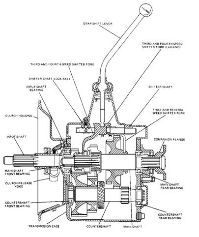
Fig. 11.6: Constant mess transmission system
(Source: http://topmech.narod.ru/Output/files/tnmfiles/OD1005/ch3.htm)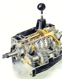
Fig. 11.7: Simple unsynchronized systems
(Source:http://wikicars.org/images/en/thumb/c/c8/Gearbox_diagram.JPG/400px-Gearbox_diagram.JPG)
For the collar shift style, the gears are built up into a stack. The gears do not slide back and forth. These gears are not splined to the main shaft but are free to rotate when not engaged. There is a shift collar in between each gear pair, i.e. 1st & 2nd or 3rd & 4th. This collar is splined to the main shaft, and is the movable component when a speed change is called for.
d) Synchronized systems:
In the system, the gearbox is of constant mesh type, in which all gears are always in mesh but only one of these meshed pairs of gears is locked to the shaft on which it is mounted at any one time, the others being allowed to rotate freely; thus greatly reducing the skill required to shift gears (Fig. 11.8). These systems that will automatically "mesh" while changing gears. Basically the same as the manual shift except it has synchronizers and can be shifted on the go. The clutch should always be used for starts, stops as well as shifting. It usually has 6-8 forward gears and 1-2 reverses.
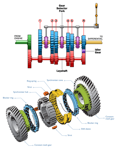
Fig. 11.8: Synchronized systems
(Source:http://static.ddmcdn.com/gif/transmission-5speed-gears.gif)
Let's suppose our transmission is synchronized between 3rd and 4th gears. We'll start out in 3rd gear, and then shift into 4th. As we shift, the first occurrence in the chain of events is that we move the transmission out of 3rd gear, and into neutral. As we continue moving the shift lever towards 4th gear, a brass cone applies friction to 4th gear, increasing or decreasing it's speed to match that of the rotating collar. Once the speeds have equalized, the gears still may not be lined up with each other, so there are little triangular shaped teeth around the outer circumference of the brass cone, which serve to ever so slightly rotate the shift collar teeth and the gear teeth into perfect alignment. This whole process occurs rapidly, usually allowing a straight-through shift, directly out of one gear and into the next. Synchro transmissions range from simple, where only a single pair of gears are synchronized, on up to full synchronization of all speeds, including forward and reverse
c) Hydrostatic Transmission:
Hydrostatic transmissions transmit all power with hydraulics i.e. with the power of oil.. One half of the transmission is a variable displacement pump and the other half is a hydraulic motor. A movable swash plate controls the piston stroke to change the pump's displacement. A hydrostatic transmission works as being a variable-displacement hydraulic pump, driving a fixed-displacement hydraulic motor (Fig. 11.9).
The greatest advantage of a hydrostatic transmission is the ability to infinitely vary the ground speed and quickly change directions. Another advantage is reliability. This transmission is self-protecting from operator abuse. Also, on foot pedal controlled transmissions, there is a built in safety factor in that you need only lift your foot from the pedal, to bring the tractor to a controlled stop. Their disadvantages are high cost, sensitivity to contamination and a slight loss of power at the PTO shaft. You must also remember to apply the parking brake when you park the tractor on a slope.
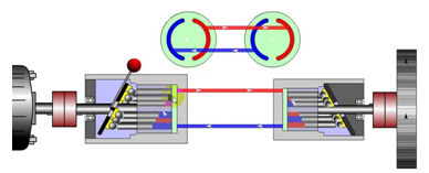
Fig. 10.9: Hydrostatic transmission
(Source:http://www.google.co.in/imgres?imgurl=&imgrefurl=http%3A%2F%2Fwww.youtube.com%2Fwatch%3Fv%3DqxZFSNITK&h=0&w=0&sz=1&tbnid=4Ga0WJ9zO7jx9M&tbnh=168&tbnw=299&zoom=1&docid=YODn5B0eKQyyFM&ei=6MPTUuT5GYLVrQe_i4GwBQ&ved=0CAIQsCUoAA)
Hydrostatic is, by far, the best choice for turf mowing applications or for any tasks that require constant speed and direction changes within a small area. They are used in the drive train of riding lawnmowers and lawn tractors and applications requiring continuously variable control.
A hydraulic automatic transmission consists of the following parts:
- Fluid coupling or Torque converter: A hydraulic device connecting the engine and the transmission. It takes the place of a mechanical clutch, allowing the engine to remain running at rest without stalling. A torque converter is a fluid coupling that also provides a variable amount of torque multiplication at low engine speeds, increasing "breakaway" acceleration.
- Planetary gear set:A compound planetary set whose bands and clutches are actuated by hydraulic servos controlled by the valve body, providing two or more gear ratios.
- Valve body:A hydraulic control center that receives pressurized fluid from a main pump operated by the fluid coupling/torque converter. The pressure coming from this pump is regulated used to run a network of spring-loaded valves, check balls and servo pistons. The valves use the pump pressure and the pressure from a centrifugal governor on the output side (as well as hydraulic signals from the range selector valves and the throttle valve or modulator) to control which ratio is selected on the gear set; as the car and engine change speed, the difference between the pressures changes, causing different sets of valves to open and close. The hydraulic pressure controlled by these valves drives the various clutch and brake band actuators, thereby controlling the operation of the planetary gear set to select the optimum gear ratio for the current operating conditions. However, in many modern automatic transmissions, the valves are controlled by electro-mechanical servos which are controlled by the Engine Management System or a separate transmission controller.
d) Continuously variable Transmission:
A different type of automatic transmission is the continuously variable transmission or CVT, which can smoothly alter its gear ratio by varying the diameter of a pair of belt or chain-linked pulleys, wheels or cones. Some continuously variable transmissions use a hydrostatic drive consisting of a variable displacement pump and a hydraulic motor to transmit power without gears. CVT designs are usually as fuel efficient as manual transmissions in city driving, but early designs lose efficiency as engine speed increases.
A slightly different approach to CVT is the concept of toroidal CVT or IVT (from infinitely variable transmission). These concepts provide zero and reverse gear ratios.
V. Tractor Transmission Performance:
The relationship between engine brake power and power in the drive wheels of tractor are discussed below.
i. Engine Brake power
The engine brake power (W) is given by the following equation
![]() ... (11.10)
... (11.10)
Where, W= engine brake power, kW
Ne = engine RPM
Te = engine torque, N-m
Or ![]() ... (11.11)
... (11.11)
Where, W= engine brake power, HP
Ne = engine RPM
Te = engine torque, Kg-m
ii. Power in the drive wheels of tractor
The power in the drive wheels of tractor is given by
![]() ... (11.12)
... (11.12)
Where, Ww = power in drive wheels of tractor, kW
Tw = drive wheel torque, N-m
Nw = drive wheel RPM
Based on torque speed relationship of tractor power transmission as given in eqns. 8.2 and 8.3, the transmission efficiency (ηt) is given by the following equation.
![]() ... (11.13)
... (11.13)
Where, Te = engine torque, N-m or Kg-m
Ne = engine RPM
Tw = drive wheel torque, N-m
Nw = drive wheel RPM
ηt = transmission efficiency, %
iii. Drawbar power of tractor
It primarily depends on drawbar pull developed by the tractor and its speed of operation. The drawbar power of tractor is given by
![]() ...(11.14)
...(11.14)
Where, Wd= drawbar power, kW
P = drawbar pull, kN
S = speed, km/hr
Or, ![]() ...(11.15)
...(11.15)
Where, Wd = drawbar power, HP
P = drawbar pull, Kg
S = speed, m/s
VI. Design Procedure for Gearbox of a Tractor
i. Design Considerations
1. To reduce the size of gearbox, the intermediate shaft should have as high speed as possible.
2. At any point of time only one set of gears should be in mesh. In other words, one set of gears must be completely disengaged before the other starts to engage.
3. The transmission ratio (TR) of a pair of gears in a gearbox should satisfy following condition.
![]()
4. The speed range ratio (Maximum shaft speed divided by minimum shaft speed) should not be more than 8.
5. In case of sliding gearbox, the centre distance between two shafts should remain constant. Or in other words the sum of number of teeth of meshing gears must be constant.
![]()
6. In a gearbox same module (m) of the gear set must be used.
7. The minimum difference between the numbers of teeth of adjacent gears must be 4.
8. The minimum numbers of teeth (in a set for spindle drives) should be greater than 17 to avoid interference of tooth.
VII. Differential
Differential of a tractor consists of planetary gear system which has four bevel gears (two side gears and two pinions). It also has a pair of bevel gears consisting of a pinion and crown wheel fitted at right angle to each other to transmit power received from the gearbox to the rear axles. In other words, the input power to the planet carrier attached to the crown wheel and output power to the side gears mounted on the counter shafts gives drive the rear wheels. It acts as a speed reduction and transmission of power at 90°. The differential divides the power into equal parts and finally to the rear wheels. It allows one wheel of tractor to move faster than the other wheel while taking turns. When the tractor is moving straight ahead, the bevel pinions of differential do not rotate on their carrier shafts and both the side gears rotate at same speed. A differential lock is also provided to prevent excessive spin of one wheel than the other when a resistance to wheel is different. If one wheel of tractor gets in the mud or loose soil, the other wheel on the solid ground will not move while the other wheel spins around due to differential action. To overcome this problem differential lock is provided which allow both the wheels to move with same speed and apply equal torque.
The torque transmitted by both the axles of tractor would be equal as the bevel pinions of differential are exerting equal torque on both the side gears.
Transmission efficiency of differential of tractor is given by
![]() ... (11.16)
... (11.16)
Where, ηd = Transmission efficiency of differential
Wa = power output through both the axles, kW
Wbp = power input to differential through bevel pinion, kW
Also,
![]() ... (11.17)
... (11.17)
Where, Tbp = torque input to bevel pinion of differential, Nm
Nbp = RPM of bevel pinion
Tal = torque output from left axle, N.m
Tar = torque output from right axle, N.m
Nal = RPM of left axle
Nar = RPM of right axle
ηd = transmission efficiency of differential, %
While moving straight, the torque in both the axles should be equal
Therefore Tal = Tar = Ta …. (11.18)
Where, Ta = rear wheel axle torque.
And average speed of the axle (Na) would be
![]() ….. (11.19)
….. (11.19)
From eqns. 11.17, 11.18 and 11.19
We get,
![]()
Or ... (11.20)
![]()
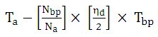 ... (11.21)
ii. Speed division by the differential
While taking turns, the role of differential comes into picture and as per the principles of differential gears, the reduction in speed of inner sun gear will be added up to the speed of outer sun gear. The speed of crown wheel during turnings would be average speed of two drive wheels of the tractor as given by following equation.
![]() ... (11.22)
... (11.22)
Where,Nc = crown wheel speed, rpm
Ni = inner wheel speed, rpm
No = outer wheel speed, rpm
iii. Design of Bevel Gears of differential
The following points should be taken into account while designing a bevel gear drive for a differential:
The gear should have sufficient strength so that, it does not fail at starting torques under dynamic running conditions.
The teeth must have very good wear characteristics so that the life of gear is long.
The suitable material must have very good wear characteristics so that life of gear is long.
The drive should be compact and properly designed.
The proper lubrication arrangement should be made.
Design procedure
1. Pitch diameters of bevel gears: Let the number of teeth be N and module be m,.
Then, ![]()
Velocity ratio =VR =1.7
Take ![]()
Thus, the reference angle for tooth of gear = 30.4º
Thus, the reference angle for tooth of pinion= 59.6º
Pitch line velocity: Pitch line velocity of pinion and gear is calculated by
![]() ...(11.23)
...(11.23)
2. Determination of Maximum Tooth Load: Assuming that the full load acts on entire length of rotor which is driven by these gears. So, the transmitted teeth load is given by
![]() ... (11.24)
... (11.24)
3. Materials for bevel gears and Designed Stresses: Let the material for gears be 15Ni2Cr1Mo15 (Nickel chromium molybdenum steel) having ultimate strength-
![]()
Taking factor of safety 2.5 for the case hardened steel
Then, design stress
![]() ...(11.25)
...(11.25)
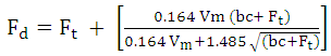
4. Dynamic load on Bevel Gears: Given in machine design hand books
![]() ... (11.26)
... (11.26)
Where, Fd = dynamic load, kgf
Cv = Velocity factor = ![]()
Vm = mean velocity
Nsf = service factor =1.5
Km = load distribution factor = 1.25
Ft = tooth load
5. Calculation of Pc and Pd : The circular pitch = Pc = λm
Diameter pitch = Pd = 1/m
6. Calculation of face width: Adopting a 20º in volute teeth (the gear Lewis form factor is given by
![]() ... (11.27)
... (11.27)
For straight bevel gears = Z1 / cos σ1 or Z1 / cos σ2 =Zv
Zv = virtual number of teeth
Z1 and Z2 = number of teeth in pinion and gear respectively
σ1 and σ2 = reference cone angle in degrees
Yv = π X Yv
Applying Lewis eqns.
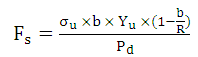 ... (11.28)
Where, Fs = strength of tooth in kgf
σu = design bending stress, 3200kg/cm2 for used material
R = cone distance
b = face width
Pd = diametrical pitch
If b is small, then we can take another value.
Check for dynamic load:
Dynamic load is given by Buckingham equation.
 … (11.29)
Where,Vm = pitch line velocity m/s
c = constant whose values for 20º full length steel gear is given by c = 11860 × e
E = permissible error in action corresponding to a pitch line velocity (V)
Therefore, Fd must be below the maximum permissible contact compressive stress.
Check for maximum wear:
Formula for maximum wear is given by
Fw =d X Q X K X b ... (11.30)
Where, Fw = wear load
d = Pitch circle diameter
Q = ratio factor 22/(2+1)
k = load factor = (σ)2 × 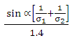 ...(11.31)
α = pressure angle
b = face width
c = design compression strength
It can be checked that Fw must be greater than Fd then only gears are safe for severe services also.
Last modified: Monday, 7 April 2014, 5:35 AM