Site pages
Current course
Participants
General
Module 1. Tractor Mechanics
Module 2. Traction
Module 3. Introduction to Transmission System
Module 4. Clutch System
Module 5. Gear Box
Module 6. Differential and Final drive
Module 7. Brakes
Module 8. Steering system
Module 9. Hydraulics
Module 10. Power Transmission
Lesson 15. Types and construction details of gear boxes
Since the torque requirement for doing the various agricultural operations is continuously varying, there is a constant need for changing the set of gears involved in transmission of the engine power to the wheels. There are a number of ways in which gears can be combined to alter the torque being supplied to the tractor wheels. A series of gears are often combined together in a Gear Box in an orderly manner.
The automobile transmission gear boxes can be classified into different categories based on the method in which the gears are meshed and speed ratios selected. Gear boxes used for transmission systems are classified into:
Sliding Mesh Gear Box
Constant Mesh Gear Box
Synchromesh Gear Box
The main components of the gear box are:
Gear Box housing
Gear shafts
Gears
Bearings
The gear box housing is the outer casing, usually made of cast iron, that houses the various shafts and gears inside. It also contains the gear box oil (SAE 90) for lubrication of the gears.
There are three types of shafts inside the gear box:
Input shaft (also called primary shaft or clutch shaft)
Counter shaft (also called lay shaft or auxiliary shaft)
Main shaft (also called secondary shaft or out shaft)
The gears on these respective shafts are called by the name of the shaft i.e. input pinion, counter shaft gear, main shaft gear.
On the primary shaft is only one gear (helical type). The primary shaft takes the rotational power from the clutch. The clutch plate is mounted on one end of this shaft, the one side which is splined. The helical gear on the primary shaft is inside the gear box housing and is meshed to another helical gear on the counter shaft. All the gears on the counter shaft are fixed to the counter shaft and rotate along with the shaft.
While construction and working of primary and counter shafts in case of all the three types of gear boxes is similar, the construction and working of the main shaft gears. The main shaft is splined, but the main shaft gears sit on the main shaft in different ways depending on which gear box these are on. The construction and working of the gear boxes is described hereunder:
Sliding Mesh Gear Box
This is the oldest and the simplest of automotive gear boxes. As the name suggests, the selected main shaft gear is slid over the main shaft to mesh with corresponding gear on the counter shaft. While the main shaft is splined, the main shaft gears are splined from inside, such that there is a positive motion between the main shaft and the main shaft gears.
At any given time, only one set (pair) of main shaft and countershaft gear are in mesh with each other. In case two pairs get meshed, they will tend to rotate the main shaft at different speeds, leading to breakage of either the main shaft or the meshed gears.
When a particular gear is to be meshed, it is slid over the main shaft by its collar and is made to mesh with the corresponding counter shaft gear.
Fig 15.1 shows the various components of a sliding mesh gear box. The gears 4, 5 and 6 on the main shaft can be slid to mesh with the corresponding gears on the counter shaft. The gear 4 is 1st gear, gear 5 is 2nd gear and gear 6 is the 3rd gear. For the 4th gear, the primary and the secondary shafts are coupled together implying that there is no speed reduction at the gear box in the 4th gear.
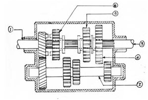
Fig 15.1 Cross-sectional view of a Sliding Mesh Gear Box
Input drive gear
Counter shaft
Main shaft
Ist gear
IInd gear
IIIrd gear
During the neutral position, none of the main shaft gears are engaged to the counter shaft gears. Depending on the speed-torque requirement, the gears of main shaft is slid to mesh with the respective gear on the counter shaft.
Constant Mesh Gear Box
In case of constant mesh type of gear box all the gears of main shaft are constantly meshed to the corresponding gears on the counter shaft as shown in the figure below:
Similar to the sliding mesh gear box, the main shaft is splined in this case too. But since all the gears on the main shaft are meshed, these are free to rotate on the splined main shaft. To transmit power an arrangement of fixed dog clutch and sliding dog clutch is used. The arrangement is shown as in the fig 15.2 below.
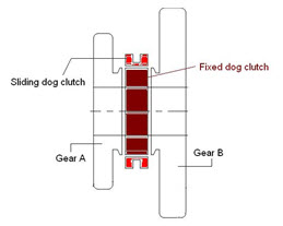
As mentioned before, the main shaft gears are free to rotate on the main shaft. The fixed dog clutch, placed between two gears is splined from inside in such a way that its rotation is associated with the main shaft i.e. when the fixed dog clutch rotates, the main shaft rotates and vice versa.
During the neutral position, the sliding dog sits on the fixed dog clutch (as shown in Fig 15.2). Now when the gear A is to be meshed, the sliding dog clutch is moved to the left so that it locks the movement of the gear to that of the fixed dog clutch. Now the gear is meshed to the corresponding gear of the counter shaft. When this gear gets locked to the fixed dog clutch, the power from the gear is transmitted to the main shaft through the fixed dog clutch. All this while the other gears continue to rotate freely on the main shaft without any interference.
In this case all the gears on the main shaft are meshed to the corresponding gears of the counter shaft. These gears are of helical type. The advantages the helical gears offer as compared to spur gears is that in case of helical gears the contact starts with a point contact thus there is less noise and it also has more area of the gear teeth in contact leading to stronger gears and higher amount of torque that can be transmitted.
While engaging the gears from neutral position, when the clutch is engaged, all the gears on main and counter shafts are rotating, but all the sliding dog clutches are in neutral position. Now to engage the gear, the clutch is disengaged, but the gears are still rotating because of their momentum, the selected sliding dog clutch is moved as per requirement towards the gear that is to be engaged. As the relative motion between the gear and the dog clutches reduces, the sliding dog clutch engages with the selected gear and the clutch can be gradually engaged.
In case of the constant mesh gear box, the clutch has to be pressed twice while moving from one gear to another. This is done in such a way that the clutch is pressed once for moving from the gear to neutral position and the second time for moving from neutral to other gear. This process of pressing the clutch twice is called double de-clutching.
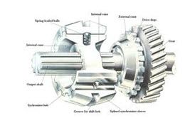
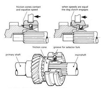
Synchromesh Gear Box
Synchromesh is an advancement over the constant mesh gear box. A synchronizing unit is provided to assisting in the gear changing.
Last modified: Monday, 3 March 2014, 5:47 AM