Site pages
Current course
Participants
General
MODULE 1. Orhtographic Projections of Machine comp...
MODULE 2. Types of joints
MODULE 3. Computer Aided drawing
MODULE 4. Numeric control systems
22 March - 28 March
29 March - 4 April
5 April - 11 April
12 April - 18 April
19 April - 25 April
26 April - 2 May
LESSON 14. Introduction to solid modeling, introduction to numeric control, basic components of NC system, NC coordinate and motion control system
14.1.Introduction
Geometric modelling in terms of wire frames uses only edges and lines which contains only geometrical data. The solid model uses topological information in addition to geometrical information to explain the object clearly and completely. The solid model also gives the information about the connectivity, associativity with the neighbourhood. The solid models are widely used in CAD/CAM programmes.
14.2.Solid modeling
Solid modeling (or modelling) is a consistent set of principles for mathematical and computer modeling of three-dimensional solids. Solid modeling is distinguished from related areas of geometric modeling and computer graphics by its emphasis on physical fidelity.[1] Together, the principles of geometric and solid modeling form the foundation of computer-aided design and in general support the creation, exchange, visualization, animation, interrogation, and annotation of digital models of physical objects.
14.3.Numeric control
Numerical control (NC) is the automation of machine tools that are operated by programmed commands encoded on a storage medium. The first NC machines were built in the 1940s and 1950s, based on existing tools that were modified with motors that moved the controls to follow points fed into the system on punched tape. These early servomechanisms were rapidly improved with analog and digital computers, creating the modern computer numerical control (CNC) machine tools.
In modern CNC systems, end-to-end component design is highly automated using computer-aided design (CAD) and computer-aided manufacturing (CAM) programs. The programs produce a computer file that is interpreted to extract the commands needed to operate a particular machine via a postprocessor, and then loaded into the CNC machines for production. Since any particular component might require the use of a number of different tools—drills, saws, etc., modern machines often combine multiple tools into a single "cell". In other cases, a number of different machines are used with an external controller and human or robotic operators that move the component from machine to machine. In either case, the complex series of steps needed to produce any part is highly automated and produces a part that closely matches the original CAD design.
14.3.1.Basic components of NC system
There are three important components of the numerical control or NC system. These are:
1) Program of instructions
2) Controller unit, also called as the machine control unit (MCU) and
3) Machine tool
14.3.1.1.Program of Instructions.
This is the detailed step by step set of instructions which tell the machine what to do. It is coded in numerical or symbolic form on some type of input medium that can be interpreted by the controller unit. The most common one is the 1-inch-wide punched tape. There are two other methods of input to the NC system. The first is by manual entry of instructional data to the controller unit. The second method of input is by means of a direct link with the computer. This is called direct numerical control, or DNC.
14.3.1.2.Controller Unit
This consists of electronics and hardware that read and interpret the program of instructions and convert it to mechanical actions of the machine tool. The typical elements of the controller unit include the tape reader, a data buffer, signal output channels to the machine tool, and the sequence controls to coordinate the overall operation of the foregoing elements.
Most N.C. tools today are provided with positive feedback controls for this purpose and are referred as closed loop systems. However there has been growth in the open loop systems which do not make use of feedback signals to the controller unit. The advocates of the open loop concept claim that the readability of the system is great enough that the feedback controls are not needed.
14.3.1.3.Machine Tool
It is part of the NC system which performs useful work. In the most common example of an NC system, one designed to perform machining operations, The machine tool consists of the worktable and spindle as well as the motors and controls necessary to drive them. It also includes the cutting tools, work fixtures and other auxiliary equipment needed in machining operation.
14.3.2. NC coordinate and motion control system
In order to use NC in manufacturing, the following steps are to be followed:
14.3.2.1.Process Planning
The engineering drawing of the work part must be interpreted in terms of the manufacturing processes to be used. this step is referred to as process planning and it is concerned with the preparation of a route sheet. The route sheet is a listing of the sequence of operations which must be performed on the work part.
14.3.2.2 Part programming
Part programming is the process of planning the sequence of machining steps to be performed by NC and to document these in a special format. There are two ways to program for NC:Manual part programming Computer-assisted part programming. In manual programming, the machining instructions are prepared on a form called a part program manuscript. This isespecially appropriate forcomplex work piece geometries and jobs with many machining steps. Use of the computer in these situations results in significant savings in part programming time.
14.3.2.3.Tape preparation
A punched tape is prepared from the part programmer’s NC process plan. In manual part programming, the punched tape is prepared directly from the part program manuscript on a typewriter.
In computer-assisted part programming, the computer interprets the list of part programming instructions, performs the necessary calculations to convert this into a detailed set of machine tool motion commands, and then controls a tape punch device to prepare the tape for the specific NC machine
14.3.2.4.Tape verification
After the punched tape has been prepared, a method is usually provided for checking the accuracy of the tape.
14.3.2.5.Production
The final step in the NC procedure to use the NC tape in production. This involves ordering the raw work parts and setting up The NC machine tool for the job. The machine tool operator's function during production is to load the raw work part in the machine and establish the starting position of the cutting tool relative to the work piece. The NC system then takes over and machines the part according to the instructions on tape. When the part is completed, the operator removes it from the machine and loads the next part.
14.4.NC Coordinate system
To plan the sequence of position and movements of the cutting tool relative to the workpiece, it is necessary to establish a standard axis system by which relative position can be specified. Using an NC drill press as an example, the drill spindle is fixed in vertical position and the table is moved and controlled relative to the spindle. To make things easier the work piece is kept stationary while the drill is moved relative to it. Accordingly , the coordinate system of axes is established with respect to the machine table. Two axis are defined as shown in figure.
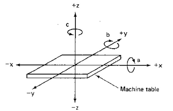
Fig.14.1 NC tool machine positioning for drilling
Two axes, x and y, are defined in the plane of the table, as shown in Figure 14.1. The Z axis is perpendicular to this plane and its movement is controlled by vertical motion of the spindle. Depending on the NC machine the part programmer may have several different options available for specifying this location.
14.4.1.Fixed Zero Versus Floating Point Zero
The programmer must determine the position of the tool relative to the origin (zero point) of the coordinate system. NC machines have either of two methods for specifying the zero point. The first possibility is for the machines to have fixed zero. In this case the origin is always located at the same position is for the machine table. Usually that position is the southwest corner of the table and all the tool locations will be defined by positive x and y coordinates.
The second and more common feature on modern NC machines allows the machine operator to set the zero point at any position on the machine table. This feature is called floating point zero. The part programmer is the one who decides where the zero point should be located. The decision is based on part programming convenience. For example the work part may be symmetrical and the zero point should be established at the centre of symmetry.
14.4.2.Absolute Versus Incremental Positioning
Another option sometimes available to the part programmer is to use either an absolute system of tool positioning or an incremental system. Absolute positioning means that the tool locations are always defined in relation to the zero point. If a hole is to drilled at the spot that is 8 inches above the X-axis and 6inches to the right of the y-axis the coordinate location of the hole would be specified as x=+6.000 and y=+8.000. By contrast incremental positioning means that the next tool locations must be defined with reference to the previous tool location.
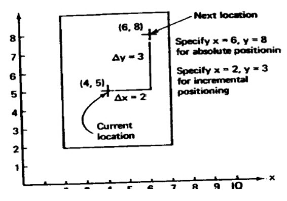
Fig.14.2.Absolute and incremental positioning
14.5.NC Motion control system
To carry out the machining process, the tool and the work piece are to be moved relative to each other. In NC there are three types of motion control systems namely,
1.Point to point
2.Straight cut
3.Contouring
The classification is concerned with the amount of control over the relative motion between the work piece and cutting tool . The least control is exerted over the tool motion with the point to point systems. Contouring represents the highest level of control.
14.5.1.Point-to-Point
This is also known as positioning system. In PTP the objective of the machine tool control system is to move the cutting tool to predefined location. Once the tool reaches the desired location, the machining operation is performed at that position. NC drill presses are a good example of PTP systems. The spindle must first be positioned at a particular location n the work piece. This is done under PTP control . Then the drilling of the holes is performed at that location, the tool is moved to the next hole location, and so forth. Since no cutting is performed between holes there is no need for controlling the relative motion of the tool and work piece between hole locations
14.5.2. Straight NC
These control systems are capable of moving the cutting tool parallel to one of the major axes at a controlled rate suitable for machining. It is therefore appropriate for performing milling operations to fabricate work pieces of rectangular configurations. With this type of NC systems is appropriate for performing milling operations to fabricate work pieces of rectangular configurations . With this type of NC system it is not possible to combine movements in more than single axis direction. Therefore angular cuts on the work piece would not be possible. An NC machine tool capable of performing straight cut movements is also capable of point to point movements.
14.5.3.Contouring NC
This is the most complex, flexible and the most expensive type of machine tool control . It is capable of performing both PTP and straight cut operations . In addition th e distinguishing feature of the of contouring NC system is their capacity for simultaneously control of more than one axis movement of machine tool Figures below illustrate the versatility of continuous path NC. Milling and Turning are the common examples of the use of contouring control.
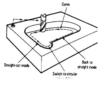 Fig.14.3.Contouring NC
Last modified: Monday, 16 September 2013, 7:28 AM