Site pages
Current course
Participants
General
Module 1. Average and effective value of sinusoida...
Module 2. Independent and dependent sources, loop ...
Module 3. Node voltage and node equations (Nodal v...
Module 4. Network theorems Thevenin’ s, Norton’ s,...
Module 5. Reciprocity and Maximum power transfer
Module 6. Star- Delta conversion solution of DC ci...
Module 7. Sinusoidal steady state response of circ...
Module 8. Instantaneous and average power, power f...
Module 9. Concept and analysis of balanced polypha...
Module 10. Laplace transform method of finding ste...
LESSON 17. Instantaneous and average power
In a purely resistive circuit, all the energy delivered by the source is dissipated in the form of heat by the resistance. In a purely reactive (indicative or capacitive) circuit, all the energy delivered by the source is stored by the inductor or capacitor in its magnetic or electric field during a portion of the voltage cycle, and then is returned to the source during another portion of the cycle, so that no net energy is transferred. When there is complex impedance in a circuit, part of the energy is alternately stored and returned by the reactive part, and part of it is dissipated by the resistance. The amount of energy dissipated is determined by the relative values of resistance and reactance.
Consider a circuit having complex impedance. Let v (t) = Vm cos wt be the voltage applied to the circuit and let i(t) = Im cost (wt+θ) be the corresponding current flowing through the circuit. Then the power at any instant of time is
P(t) = v(t) i (t)
= Vm cost wt Im cost (wt+θ) \[..................................................\left( {17.1} \right)\]
From Eq. 17.1, we get
\[P\left( t \right)=\,{{{V_m}{I_m}} \over 2}\,\left[ {\cos \,(2\omega t + \theta ) + \cos \theta } \right]..................................................\left( {17.2} \right)\]
Equation 17.2 represents instantaneous power. It consists of two parts. One is a fixed part, and the other is time-varying which has a frequency twice that of the voltage of current waveforms. The voltage, current and power waveforms are shown in figs. 17.1 and 17.2.
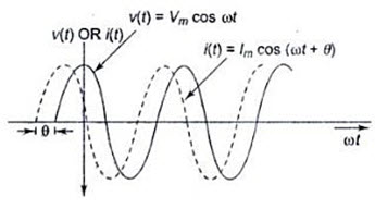 Fig. 17.1
Here, the negative portion (hatched) of the power cycle represents the power returned to the source. Figure 17.2 shows that the instantaneous power is negative whenever the voltage and current are of opposite sign. In fig. 17.2, the positive portion of the power is greater than the negative portion of the power, hence the average power is always positive, which is almost equal to the constant part of the instantaneous power (Eq. 17.2).
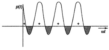
Fig. 17.2
The positive portion of the power cycle varies with the phase angle between the voltage and current waveforms. If the circuit is pure resistive, the phase angle between voltage and current is zero; then there is no negative cycle in the P (t) curve. Hence, all the power delivered by the source is completely dissipated in the resistance.
P(t) = v (t) i (t)
= Vm Im cos2 wt
\[=\,{{{V_m}{I_m}} \over 2}\left( {1 + \cos 2\,{\rm{ }}\omega t} \right)..................................................\left( {17.3} \right)\]
The waveform for Eq.17.3, is shown in fig. 17.3, where the power wave has a frequency twice that of the voltage or current. Here the average value of power is Vm Im/2.
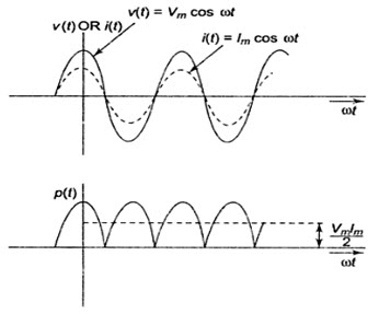
Fig. 17.3
When phase angle θ is increased, increased, the negative portion of the power cycle increases and lesser power is dissipated. When θ becomes \[pii\]2, the positive and negative portions of the power cycle are equal. At this instant, the power dissipated in the circuit is zero, i.e. the power delivered to the load is returned to the source.
17.2 Average power
To find the average value of any power function, we have to take a particular time interval from t1 to t2; by integrating the function from t1 to t2 and dividing the result by the time interval t2-t1, we get the average power.
Average power \[P={1 \over {{t_2} - {t_1}}}\int\limits_{{t_1}}^{{t_2}} {P\left( t \right)dt} ..................................................\left( {17.4} \right)\]
In general, the average value over one cycle is
\[{P_{av}}={1 \over T}\int\limits_{{0_1}}^T {P\left( t \right)dt} ..................................................\left( {17.5} \right)\]
By integrating the instantaneous power P(t) in Eq. 17.5 over one cycle, we get average power
\[{P_{av}}={1\over T}\,\,\int\limits_0^T{}\left\{{{{{V_m}{I_m}}\over 2}\left[{\cos\left({2\omega t+\theta}\right)+\cos \theta } \right]\,dt} \right\}\]
\[={1 \over T}\,\,\int\limits_0^T {{{{V_m}{I_m}} \over 2}\left[ {\cos \left( {2\omega t + \theta } \right)} \right]\,\,\,dt\,\, + \,{1 \over T}\,\int\limits_0^T {{{{V_m}{I_m}} \over 2}\cos \theta \,dt} } ..................................................\left( {17.6} \right)\]
In Eq.17.6, the first term becomes zero, and the second term remains. The average power is therefore
\[{P_{av}}={{{V_m}{I_m}} \over 2}\cos \,\,\,\,\theta \,W..................................................\left( {17.7} \right)\]
We can write Eq. 17.7 as
\[{P_{av}}=\left( {{{{V_m}} \over {\sqrt 2 }}} \right)\,\,\left( {{{{I_m}} \over {\sqrt 2 }}} \right)\cos \,\,\,\theta ..................................................\left( {17.8} \right)\]
In Fq. 6.8, \[V{}_m/\sqrt 2 \,\,and\,\,{I_m}/\sqrt 2 \,\,\] are the effective values of both voltage and current.
\[{P_{av}}\,=\,{V_{eff}}\,{I_{eff}}\,\cos \,\theta\]
To get average power, we have to take the product of the effective values of both voltage and current multiplied by cosine of the phase angle between voltage and the current.
If we consider a purely resistive circuit, the phase angle between voltage and current is zero. Hence, the average power is
\[{P_{av}}={1 \over 2}{V_m}{I_m}={1 \over 2}I_m^2R\]
If we consider a purely reactive circuit (i.e. purely capacitive or purely inductive), the phase angle between voltage and current is 900. Hence, the average power is zero or Pav = o.
If the circuit contains complex impedance, the average power is the power dissipated in the resistive part only.
Last modified: Thursday, 26 September 2013, 10:17 AM