Site pages
Current course
Participants
General
MODULE 1.
MODULE 2.
MODULE 3.
MODULE 4.
MODULE 5.
MODULE 6.
MODULE 7.
MODULE 8.
MODULE 9.
26 April - 2 May
Lesson 3. Chain Surveying
3.1 PRINCIPLE OF CHAIN SURVEYING
The principle of chain surveying is triangulation. This means that the area to be surveyed is divided into a number of small triangles which should be well conditioned. In chain surveying the sides of the triangles which should be well conditioned. In chain surveying the sides of the triangles are measured directly on the field by chain or tape, and no angular measurements are taken. Here, the tie lines and check lines control the accuracy of work.
It should be noted that plotting triangles requires no angular measurements to be made, if the three sides are known.
Chain surveying is recommended when:
The ground surface is more or less level
A small area is to be surveyed
A small-scale map is to be prepared and
The formation of well-conditioned triangles is easy
Chain surveying is unsuitable when:
The area is crowded with many details
The area consists of too many undulations
The area is very large and
The formation of well-conditioned triangles becomes difficult due to obstacles
A. Large-Scale and Small-Scale Maps
When 1 cm of a map represents a small distance, it is said to be a large-scale map.
For example,
![]()
When 1 cm of the map represents a large distance, it is called a small-scale map.
For example,
![]()
A map having an RF of less than 1/500 is considered to be large-scale. A map of RF more than 1/500 is said to be small-scale.
3.2 WELL-CONDITIONED AND ILL-CONDITIONED TRIANGLES
A triangle is said to be well-conditioned when no angle in it is less than 300 or greater than 1200 . An equilateral triangle is considered to be the best-condition or ideal triangle
Well-conditioned triangles are preferred because their apex points are very sharp and can be located by a single ‘dot’. In such a case, there is no possibility of relative displacement of the plotted point.
A triangle in which an angle is less than 300 or more than 1200 is said to be ill-conditioned
Well - conditioned triangles are not used in chain surveying. This is because their apex points are not sharp and well defined, which is why a slight displacement of these points may cause considerable error in plotting.
3.3 RECONNAISSANCE SURVEY AND INDEX SKETCH
Before the commencement of any survey work, the area to be surveyed is thoroughly examined by the surveyor, who then thinks about the possible arrangement of the framework of survey. This primary investigations of the area is termed as reconnaissance survey or reconnoitre.
During reconnaissance survey, the surveyor should walk over the area and note the various obstacles and whether or not the selected stations are intervisible. The main stations should be so selected that they enclose the whole area. The surveyor should also take care that
The neat hand sketch of the area which is prepared during reconnaissance survey is known as the ‘index sketch’ or ‘key plan’. The index sketch shows the skeleton of the survey work. It indicates the main survey stations, sub-stations, tie stations, base line, arrangement for framework of triangles and the approximate positions of different objects. This sketch is an important document for the surveyor and for the person who will plot the map. It should be attached to the starting page of the field book
3.4 DEFINITIONS AND ILLUSTRATIONS
A. Survey Stations
Survey stations are the points at the beginning and the end of a chain line. They may also occur at any convenient points on the chain line. Such stations may be:
-
Main stations
-
Subsidiary stations and
-
Tie stations
- Main stations Stations taken along the boundary of an area as controlling points are known as ‘main survey lines’. The main survey lines should cover the whole area to be surveyed. The main stations are denoted by ‘ ’ with letters A, B, C, D, etc. The chain lines are denoted by “__ … __ ... __...__...__...__”.
- Subsidiary stations Stations which are on the main survey lines or any other survey lines are known as “Subsidiary stations”. These stations are taken to run subsidiary lines for dividing the area into triangles, for checking the accuracy of triangles and for locating interior details. These stations are denoted by ‘’ with letters S1,S2,S3, etc.
- Tie stations These are also subsidiary stations taken on the main survey lines. Lines joining the tie stations are known as tie lines. Tie lines are mainly taken to fix the directions of adjacent sides of the chain survey map. These are also taken to form ‘chain angles’ in chain traversing, when triangulation is not possible. Sometimes tie lines are taken to locate interior details. Tie stations are denoted by ‘’ with letters T1, T2, T3. Etc.
B. Base Line
The line on which the framework of the survey is built is known as the ‘base line’. It is the most important line of the survey. Generally, the longest of the main survey lines is considered the base line. This line should be taken through fairly level ground, and should be measured very carefully and accurately. The magnetic bearings of the base line are taken to fix the north line of the map.
C. Check Line
The line joining the apex point of a triangle to some fixed point on its base is known as the ‘check line’. It is taken to check the accuracy of the triangle. Sometimes this line helps to locate interior details.
D. Offset
The lateral measurement taken from an object to the chain line is known as ‘offset’. Offsets are taken to locate objects with reference to the chain line. They may be of two kinds - perpendicular and oblique.
1. Perpendicular offsets When the lateral measurements are taken perpendicular to the chain line, they are known as perpendicular offsets
Perpendicular offsets may be taken in the following ways:
(a) By setting a perpendicular by swinging a tape from the object to the chain line. The point of minimum reading on the tape will be the base of the perpendicular
(b) By setting a right angle in the ratio 3 : 4 : 5
(c) By setting a right angle with the help of builder’s square or tri-square
(d) By setting a right angle by cross-staff or optical square.
2. Oblique offsets Any offset not perpendicular to the chain line is said to be oblique. Oblique offsets are taken when the objects are at a long distance from the chain line or when it is not possible to set up a right angle due to some difficulties. Such offsets are taken in the following manner.
Suppose AB is a chain line and p is the corner of a building. Two points ‘a’ and ‘b’ are taken on the chain line. The chainages of ‘a’ and ‘b’ are noted. The distances ‘ap’ and ‘bp’ are measured and noted in the field book. Then ‘ap’ and ‘bp’ are the oblique offsets. When the triangle abp is plotted, the apex point p will represent the position of the corner of the the building.
Perpendicular offsets are preferred for the following reasons:
(a) They can be taken very quickly
(b) The progress of survey is not hampered
(c) The entry in the field book becomes easy
(d) The plotting of the offsets also becomes easy
3. Number of offsets The offsets should be taken according to the nature of the object. So, there is no hard and fast rule regarding the number of offsets. It should be remembered that the objects are to be correctly represented and hence the number of offsets should be decided on the field. Some guidelines are given below:
(a) When the boundary of the object is approximately parallel to the chain line, perpendicular offsets are taken at regular intervals
(b) When the boundary is straight, perpendicular offsets are taken at both ends of it
(c) When the boundary line is zigzag, perpendicular offsets are taken at every point of bend to represent the shape of the boundary accurately. In such a case, the interval of the offsets may be irregular
(d) When a road crosses the chain line perpendicularly, the chainage of the intersection point is to be noted
(e) When a road crosses a chain line obliquely, the chainages of intersection points ‘a’ and ‘b’ are noted. Then at least one offset is taken on both sides of the inter-section points. More offsets may be taken depending on the nature of the road. Here, perpendicular offsets are taken at ‘c’ and ‘d’
(f) When the building is small, its corners are fixed by perpendicular or oblique offsets and the other dimensions are taken directly on the field and noted in the field book.
(g) When the building is large, zigzag in shape and oblique to the chain line, then the corners are fixed by perpendicular or oblique offsets. Then the full plan of the building is drawn on a separate page along with all the dimensions. This page should be attached with the field book at the proper place.
(h) When the object is circular, perpendicular offsets are taken at short and regular intervals
4. Limiting length of offset The maximum length of the offset should not be more than the length of the tape used in the survey. Generally, the maximum length of offset is limited to 15m. However, this length also depends upon the following factors:
(a) The desired accuracy of the map
(b) The scale of the map
(c) The maximum allowable deflection of the offset from its true direction and
(d) The nature of the ground
Problems on limiting length of offset
Problem 1 An offset was laid out 50 from its true direction and the scale of the map was 20 m to 1 cm. Find the maximum length of offset for the displacement of a point on the paper not to exceed 0.03 cm.
Solution Let AB be the actual length of offset which was laid out 50 from its true direction. So, BC is the displacement of the point.
Let the maximum length of offset, AB = L m
![]()
or BC = AB sin 50 = L sin 50 m (displacement of the ground)
Since the scale is 1 cm to 20 m, 20 m on the ground represents 1 cm on the paper.

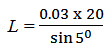
= 6.884 m
Therefore, the maximum length of offset should be 6.884 m.
Problem 2 The length of the offset is 15 m and the scale of the plan 10 m to 1 cm. If the offset is laid out 30 from its true direction, find the displacement of the plotted point on the paper
(i) perpendicular to the chain line, and
(ii) parallel to the chain line.
Solution Let AB be the actual length of offset, which is 15 m long and deflected by 30 from its true direction.
Here,
BC = Displacement parallel to chain line
CD = displacement perpendicular to chain line
(i) CD = AD – AC = AB - AC
= 15 – 15 cos 30
= 15 (1 – cos 30) m (displacement on the ground)
Since the scale is 1 cm to 10 m,
10 m on the ground = 1 cm on the map
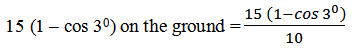
= 0.002 cm on the map
Required displacement perpendicular to chain line
= 0.002 cm (on paper)
(ii) BC = AB sin 30 = 15 sin 30 = 0.7850 m (displacement on ground)
![]()
E. Degree of Accuracy
Degree of accuracy is determined before the starting of any survey work. It is worked out according the following factors:
(a) Scale of plotting
(b) Permissible error in plotting
During reconnaissance survey, the length of the main survey lines are approximately determined by the pacing method. One pace or walking step of a man is considered to equal 80 cm. When the length of the survey lines or the extent of area to be surveyed is approximately known, the scale of the map may be assumed. Again, the permissible error in plotting may be obtained from the concerned department. Then the degree of accuracy in measurement is ascertained.
Let us now consider an example.
Suppose the scale of plotting is 5 m to 1 cm and the allowable error is 0.02 cm.
Then, 1 cm on the map = 500 cm on the ground
0.02 cm on the map = 500 x 0.02 = 10 cm on the ground
So, the measurement should be taken nearest to 10 cm.
3.5 SELECTION OF SURVEY STATIONS
The following points should be remembered during the selection of survey stations:
The stations should be so selected that the general principle of surveying may be strictly followed.
The stations should be intervisible.
The stations should be selected in such a way that well-conditioned triangles may be formed.
The base line should be the longest of the main survey lines.
The survey lines should be taken through fairly level ground, as far as practicable.
The main survey lines should pass close to the boundary line of the area to be surveyed.
The survey lines should be taken close to the objects so that they can be located by short offsets.
The tie stations should be suitably selected to fix the directions of adjacent sides.
The subsidiary stations should be suitably selected for taking check lines.
Stations should be so selected that obstacles to chaining are avoided as far as possible.
The survey lines should not be very close to main roads, as survey work may then be interrupted by traffic.
3.6 EQUIPMENTS FOR CHAIN SURVEY
The following equipments are required for conducting chain survey:
Metric chain (20 m) = 1 no.
Arrows = 10 nos.
Metallic tape (15 m) = 1 no.
Ranging rods = 3 nos.
Offset rod = 1 no
Clinometer = 1 no
Plumb bob with thread = 1 no
Cross staff or optical square = 1 no
Prismatic compass with stand = 1 no.
Wooden pegs = 10 nos.
Mallet = 1 no
Field book = 10 nos.
Good pencil = 1 no
Pen knife = 1 no.
Eraser (rubber) = 1 no.
3.7 THE FIELD BOOK
The notebook in which field measurements are noted is known as the ‘field book’. The size of the field book is 20 cm x 12 cm and it opens lengthwise. Field books may be of two types:
Single –line , and
Double-line.
1. Single-line field book In this type of field book, a single red line is drawn through the middle of each page. This line represents the chain line, and the chainages are written on it. The offsets are recorded, with sketches, to the left or right of the chain line. The recording of the field book is started from the last page and continued towards the first page. The main stations are marked by ‘’ and subsidiary stations or tie stations are by ‘’
2. Double-line field book In this type of field book, two red lines, 1.5 cm apart, are drawn through the middle of each page. This column represents the chain line, and the chainages are written in it. The offsets are recorded, with sketches, to the left or right of this column. The recording is begun from the last page and continued towards the first. The main stations are marked by ‘’ and subsidiary or tie stations by ‘’ This type of field book is commonly used.
A. Problems on Entering Records in Field Book
Problem 1 While measuring a chain line AB, the following offsets are taken. How would you enter the field book ?
(a) A telegraph post is 10 m perpendicularly from chainage 2.5 m to the right of the chain line.
(b) A road crosses obliquely from left to right at chainage 10 m and 14 m. Perpendicular offsets are 2m and 3m to the side of the road from chainage 5m and 20 m respectively.
(c) A tube-well is 5m perpendicularly from chainage 30 m to the left of the chain line.
(d) Total chainage of AB is 45 m.
Problem 2 The base line AC of a chain survey is measured and the following records are noted. Make the necessary entries in a field book.
(a) The corners of a building are 9 and 9,5m from chainage 7.5 and 18 m to the left of the chain line. The building is 7m wide.
(b) A 4 m wide road runs about parallel to the right of the chain line. Offsets are 2,2.1,2.2, and 2.15m at chainages 0,20,40, and 55.5m respectively.
(c) A check line is taken from the sub-station at chainage 25 m to the left.
(d) The total chainage of the base line is 55.5m.
(e) The fore bearing and back bearing of the base line are 30030’ and 21003C’ respectively.
Problem 3 Enter the field book according to the following field notes:
(a) Chainage of line AB is 95.5m
(b) The offsets to the pond at the left of chain line are as follows:
Chainage – 10,15,20,25,30 m
Offset – 16,12,10,14,20 m
(c) The offsets to the river at the right of the chain line are :
Chainage – 5,25,40,80 m
Offset -13,17,19,19.5m
B. Precautions to be Taken While Entering the Field book
1. All measurements should be noted as soon as they are taken.
2. Each chain line should be recorded on a separate page. Normally it should start from the bottom of one page and end on the top of another. No line should be started from any intermediate position.
3. Over –writing should be avoided.
4. Figures and hand-writing should be neat and legible.
5. Index-sketch, object-sketch and notes should be clear.
6. Reference sketches should be given in the field book, so that the station can be located when required.
7. The field book should be entered in pencil and not in ink.
8. If an entry is incorrect or a page damaged, cancel the page and start the entry from a new one.
9. Erasing a sketch, measurement or note should be avoided.
10. The surveyor should face the direction of chaining so that the left-hand and right-hand objects can be recorded without any confusion.
11. The field-book should be carefully preserved.
12. The field-book should contain the following:
(i) name,
(ii) location, and
(iii) date, of survey,
(iv) name of party members, and
(v) page index or chain line.
3.8. PROCEDURE OF FIELD WORK
Field work of chain survey should be carried out according to the following steps:
1.Reconnaissance
Before starting survey work, the surveyor should walk over the whole area to be surveyed in order to examine the ground and determine the possible arrangement of framework of survey. During this investigation, he should examine the intervisibility of the main survey stations. He should ensure that the whole area is enclosed by main survey lines, and also that it is possible to form well-conditioned triangles. He should observe various objects and boundary lines carefully and select the survey lines in such a manner that the objects can be located by short offsets. The base line should preferably be taken through the centre of the area and on fairly level ground.
2.Index sketch
After preliminary inspection of the area, the surveyor should prepare a neat hand sketch showing the arrangement of the framework and approximate position of the objects. He should note the names of the stations on the sketch maintaining some order (clockwise or anticlockwise). The field work should be executed according to this index sketch. The names and sequence of chain lines should be followed as directed in the index sketch. The ‘base line’ should be clearly indicated in the index sketch.
3. Marking the stations on the ground
After reconnaissance, the stations are marked on the ground by wooden pegs. These pegs are generally 2.5 cm square and 15 cm long, and have pointed ends. They are driven into the ground firmly, and there should be a height of 2.5 cm above the ground. The station point is marked with a cross so that it can be traced if the wooden peg is removed by somebody
4. Reference sketches
To take precautions against station pegs being removed or missed, a reference sketch should be made for all main stations. It is nothing but a hand sketch of the station showing at least two measurements from some permanent objects. A third measurement may also be taken
5.Taking measurements of survey lines and noting them in the field book
Ranging and chaining is started from the base line, which should be measured carefully. The magnetic bearings of the base line are measured by prismatic compass. These measurements are noted in the field book showing the offsets to the left or right according to their position. Then the other survey lines are ranged and chained maintaining the sequence of the traverse. The offsets and other field records are noted simultaneously. The check lines and tie lines are also measured and noted at the proper place. The station marks are preserved carefully until field work is completed.
3.9 CONVENTIONAL SYMBOLS
In a map the objects are shown by symbols and not by names. So the surveyor should know the following standard conventional symbols for some common objects.
EQUIPMENTS FOR PLOTTING
1. Drawing board (normal size – 1000 mm x 700 mm)
2. Tee-square
3. Set-square (450 and 600)
4. Protractor
5. Cardboard scale – set of eight
6. Instrument box
7. French curve
8. Offset scale
9. Drawing paper of good quality (normal size – 880 mm x 625 mm)
10. Pencils of good quality – 2 H, 3 H or 4 H
11. Eraser (rubber) of good quality
12. Board clips or pins
13. Ink (Chinese ink or Indian ink) of required shade
14. Colour of required shade
15. Inking pen (or Hi-tech pen) and brushes
16. Handkerchief, knife , paperweight, etc.
17. Mini drafter
3.10 PROCEDURE OF PLOTTING
1. A suitable scale is chosen so that the area can be accommodated in the space available on the map.
2. A margin of about 2 cm from the edge of the sheet is drawn around the sheet.
3. The title block is prepared on the right hand bottom corner.
4. The north line is marked on the right-hand top corner, and should preferably be vertical. When it is not convenient to have a vertical north line, it may be inclined to accommodate the whole area within the map.
5. A suitable position for the base line is selected on the sheet so that the whole area along with all the objects it contains can be drawn within the space available in the map.
6. The framework is completed with all survey lines, check lines and tie lines. If there is some plotting error which exceeds the permissible limit, the incorrect lines should be resurveyed.
7. Until the framework is completed in proper form, the offsets should not be plotted.
8. The plotting of offsets should be continued according to the sequence maintained in the field book.
9. The main stations, substations, chain line, objects, etc. should be shown as per standard symbols
10. The conventional symbols used in the map should be shown on the right-hand side.
11. The scale of the map is drawn below the heading or in some suitable space. The heading should be written on the top of the map.
12. Unnecessary lines, objects etc. should be erased.
13. The map should not contain any dimensions.
Inking of the map
The inking should be begun from the left-hand-side towards the right-hand-side, and from the top towards the bottom.
Colouring of the map
In general, colour washing of engineering survey maps is not recommended. However, if it is necessary, the colour shades should be very light, and according to the colour conventions. The colouring should also be started from the left-hand-side towards the right and from the top towards the bottom.
3.11 CROSS-STAFF AND OPTICAL SQUARE
A. Cross-staff
The cross-staff is a simple instrument for setting out right angles. There are three types of cross-staves.
Open
French
Adjustable
The open cross-staff is commonly used.
Open cross-staff
The open cross-staff consists of four metal arms with vertical slits. The two pairs of arms (AB and BC) are at right angles to each other. The vertical slits are meant for sighting the object and the ranging rods. The crossstaff is mounted on a wooden pole of length 1.5m and diameter 2.5 cm. The pole is fitted with an iron shoe.
For setting out a perpendicular on a chain line, the cross-staff is held vertically at the approximate position. Suppose slits A and B are directed to the ranging rods (R, R1) fixed at the end stations. Slits C and D are directed to the object (O). Looking through slits A and B, the ranging rods are bisected. At the same time, looking through slits C and D, the object O is also bisected. To bisect the object and the ranging rods simultaneously, the cross staff may be moved forward or backward along the chain line
B. Optical Square
An optical square is also used for setting out right angles. It consist of a small circular metal box of diameter 5 cm and depth 1.25 cm. It has a metal cover which slides round the box to cover the slits. The following are the internal arrangements of the optical square.
1. A horizon glass H is fixed at the bottom of the metal box. The lower half of the glass is unsilvered and the upper half is silvered.
2. A index glass I is also fixed at the bottom of the box which is completely silvered.
3. The angle between the index glass and horizon glass is maintained at 450.
4. The opening ‘e’ is a pinhole for eye E, ‘b’ is a small rectangular hole for ranging rod B, ‘P’ is a large rectangular hole for object P.
5. The line EB is known as horizon sight and IP as index sight.
6. The horizon glass is placed at an angle of 1200 with the horizon sight. The index glass is placed at an angle of 1050 with the index sight.
7. The ray of light from P is first reflected from I, then it is further reflected from H, after which it ultimately reaches the eye E
Principle
According to the principle of reflecting surfaces, the angle between the first incident ray and the last reflected ray is twice the angle between the mirrors. In this case, the angle between the mirrors is fixed at 450. So, the angle between the horizon sight and index sight will be 900.
Setting up the perpendicular by optical square
The observer should stand on the chain line and approximately at the position where the perpendicular is to be set up.
The optical square is held by the arm at the eye level. The ranging rod at the forward station B is observed through the unsilvered portion on the lower part of the horizon glass.
Then the observer looks through the upper silvered portion of the horizon glass to see the image of the object P.
Suppose the observer finds that the ranging rod B and the image of object P do not coincide. The he should move forward or backward along the chain line until the ranging rod B and the image of P exactly coincide
At this position the observer marks a point on the ground to locate the foot of the perpendicular.
Last modified: Wednesday, 30 October 2013, 8:50 AM