Site pages
Current course
Participants
General
MODULE 1.
MODULE 2.
MODULE 3.
MODULE 4.
MODULE 5.
MODULE 6.
MODULE 7.
MODULE 8.
MODULE 9.
Topic 10
LESSON 15. Theodolite –description of the instrument & Traversing
THEODOLITE
- Theodolite is an instrument used to measure horizontal and vertical angles.
The most important instrument for exact survey work, and many types are available to meet varying requirements of accuracy and precision, with direct readings of the circle ranging from 5 min to 0.1 sec.
Uses of Theodolite
i) Measurement of Horizontal and vertical angles.
ii) Setting out lines and angles
iii) Optical distance measurement
iv) Plumbing tall building
v) Setting out of Railway curves
vi) Locating the position of piers for Bridge etc.
vii) Geographical position fixing from observation of sun and stars.
viii) Alignment control in tunnel construction.
CLASSIFICATION
Theodolite may be classified into transit and non-transit theodolites.
- Transit theodolite
- A theodolite is said to be transit one when its telescope can be revolved through 180° in a vertical plane about its horizontal axis, thus directing the telescope in exactly opposite direction.
- Non-transit theodolite
- A theodolite is said to be a non-transit one when its telescope cannot be revolved through 180° in a vertical plane about its horizontal axis.
TYPE OF THEODOLITE
In general, theodolite is divided into three types based on angles, which are vernier, optical and electronic.
- Vernier Theodolite
- Uses vernier scale
- Optical Theodolite
- Uses optical with horizontal and vertical circles made from transparent glasses and graduated scale
- Electronic Theodolite
- Has a screen with digits for angles on front and back of the instrument.
- The face of the current observation (telescope position) is the side on which the vertical circle is, when viewed from the eyepiece, which is either face left or face right
- The telescope has its own clamp and tangent screws. (The clamp screws require only finger tip pressure)
- Basically Transit Theodolite are those in which the telescope can revolve through a complete revolution about its Horizontal axis in vertical plane.
- Components of Transit theodolite
Transit theodolite consists of the following parts :
1. Levelling Head
2. Lower Plate or Scale Plate
3. Upper Plate or Vernier Plate
4. The standard or A Frame
5. T-Frame or Index Bar.
6. Plate Levels
7. Telescope
1. Levelling Head - Levelling Head consists of upper tribrach and lower Tribrach. Upper tribrach has three arms, each arm carries a levelling screw for levelling the equipment. Lower tribrach has got a circular hole through which a plumb bob may be suspended for centering.
Three distinct functions of levelling head are:
i) to support the main part of the instrument
ii) to attach the Theodolite to the Tripod
iii) to provide a means for levelling the theodolite
2. Lower Plate (Scale Plate) : Lower Plate which is attached to outer spindle, carries a horizonta graduated circle, it is graduated from 0-360. Each degree is further divided into 10 minutes or 20 minutes. Scale plate can be clamped to any position by a clamping screw and a corresponding slow motion screw.
When the lower plate is tightened, the lower plate is fixed to the upper tribrach of the levelling head. The size of the Theodolite is determined by the size of the diameter of this lower plate.
3. Upper plate or Vernier Plate : Upper plate is attached to Inner spindle axis. Two verniers are screwed to the upper plats. It carries an upper clamp screw and tangent screw. On clamping the upper clamp and unclamping the lower clamp, the instrument may be rotated on its outer spindle without any relative motion between the two plates.
On the other hand if lower clamp screw is tightened and upper clamp screw is unclamped, the instrument may be rotated about its inner spindle with a relative motion between the vernier and graduated scale of the lower plate. This property is utilised for measuring angles.
4. Plate Levels - Upper plates carries two plate levels placed at right angles to each other. One of the plate bubble is kept parallel to the trunion axis. Plate levels can be centred with the help of foot screws.
5. Telescope – Telescope is supported on the pivots of the trunion axis which affords its movement in the vertical plane.
IMPORTANT DEFINITIONS –
i) Line of Collimation - the line which passes through the Intersection of the cross hairs of the eye piece and optical centre of the objective and its continuation is called as line of collimation. This is also known as line of sight.
ii) Transiting - The process of turning the telescope in vertical plane through 180 deg. about its horizontal axis is known as transiting.
iii) Swing - A continuous motion of telescope about the vertical axis in horizontal plane is called swing. The swing may be in either direction i.e. Right swing or left swing.
iv) Face left observation – When vertical circle is on the left of the telescope at the time of observation, the observations are called face left observation.
v) Face right observation – When vertical circle is on the right of the telescope at the time of observation.
ADJUSTMENT OF A THEODOLITE
The adjustments of a theodolite are of two kinds:
-
Permanent adjustment
-
Temporary adjustment
PERMANENT ADJUSTMENT
- The permanent adjustment are made to establish the fixed relationships between the fundamental lines of the instrument, and once made, they last for long time.
- They are essential for the accuracy of observations. The permanent adjustment in case of transit theodolite are:
-
Adjustment of the Horizontal Plate Levels.
-
Collimation Adjustment
-
Horizontal Axis Adjustment
-
Adjustment of the Telescope Level or the Altitude level.
-
Vertical Circle Index Adjustment.
TEMPORARY ADJUSTMENT OF THEODOLITE
The temporary adjustments are made at each set up of the instrument before starting taking observations with the instrument.
1) Setting up the Theodolite over the station
2) Levelling up the theodolite
3) Elimination of the parallax
1. Setting up : Operation of setting up a theodolite includes:
a) centering the theodolite over the ground mark
b) approximate levelling with the help of tripod legs.
2. Levelling up of theodolite
The operation of making the vertical axis truly vertical is known as levelling of Theodolite.
i) Turn the horizontal plate until the longitudinal axis of the plate level is
approximately parallel to a line joining any two levelling screws.
ii) Bring the bubble to the centre of its run by turning both foot screws simultaneously in opposite directions either inwards or outwards. The movement of the left thumb indicates the direction of movement of bubble.
iii) Turn the instrument through 1800 in azimuth.
iv) Note the position of the bubble. If it occupies a different position, move it by means of the same two foot screws to the approx. mean of the two positions.v) Turn the theodolite through 90 in azimuth so that the plate level becomes perpendicular to the previous position.
vi) With the help of third floor screw, move the bubble to the approx. mean position already indicated.
vii) Repeat the process until the bubble, retains the same position for every setting of the instrument.
3. Elimination of Parallax : Elimination of parallax may be done by focusing the eye piece for distinct vision of cross hairs and focusing the objective to bring the image of the object in the plane of cross hairs.
Measurement of Horizontal Angle
Procedure : to measure a Horizontal Angle ABC between BA & BC the following procedure is followed.
-
Set up, Centre and level the theodolite over the ground point B.
-
Loosen the upper plate, set the vernier to read zero and clamp the upper clamp.
-
Loosen the lower plate and swing the telescope until the left point A is sighted. Tighten the lower clamp. Accurate bisection of the arrow held on the Point A is done by using the lower tangent screw. Read both the vernier and take the mean of the reading.
-
Unclamp the upper plate and swing the telescope in clockwise direction until point C is brought in the field of view. Tighten the upper clamp and bisect the mark of C accurately, using the upper clamp tangent screw.
-
Read both the verniers and take the mean of readings. The difference of the means of the reading to C to A is the required angle ABC.
-
Change the face of the instrument and repeat the show procedure, the measure of the angle is again obtained by taking the difference of the means of the readings to C&A on face right.
-
The mean of the two measures of the angle ABC on two faces is the required value of the angle ABC.
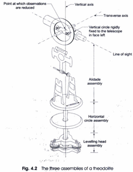
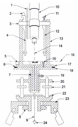
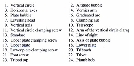
Fig 9.1 Parts of theodolite
Fig 9.2 Measurement with thodolite
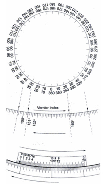
Fig 9.3 Reading a theodolite
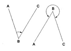
Fig 9.4 Measurement of Angle ABC
Measurement of Angle ABC
-
The instrument is set over B.
-
The lower clamp is kept fixed and upper clamp is loosened.
-
Turn the telescope clockwise set vernier A to 0° and vernier B to approximately 180°.
-
Upper clamp is tightened and using the upper tangent screw the vernier A and B are exactly set to 0° and 180°.
-
Upper clamp is tightly fixed, lower one is loosened and telescope is directed towards A and bisect the ranging rod at A.
-
Tightened the lower clamp and turn the lower tangent screw to perfectly bisect ranging rod at A.
-
Loose the upper clamp and turn the telescope clockwise to bisect the ranging rod at C tightened the upper clamp and do the fine adjustment with upper tangent screw.
-
The reading on vernier A and B are noted. Vernier A gives the angle directly and vernier B gives the reading by subtracting the initial reading (180°) from final reading
Vertical angle measurement-1
- The theodolite is set up at O. It is centred and levelled properly. The zeros of the vernires (generally C and D) are set at the 0° - 0° mark of the vertical circle (which is fixed to the telescope). The telescope is then clamped.
- The plate bubble is brought to the centre with the help of food screws (in the usual manner). Then the altitude bubble is brought to the centre by means of a clip screw. At this position the line of collimation is exactly horizontal.
- To measure the angle of elevation, the telescope is raised slowly to bisect the point A accurately. The readings on both the verniers are noted, and the angle of elevation recorded.
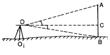
- The face of the instrument is changed and the point A is again bisected.The readings on the verniers are noted. The mean of the angles of the observed is assumed to be the correct angle of elevation.
- To measure the angle of depression, the telescope is lowered slowly and the point B is bisected. The readings on the verniers are noted for the two observations (face left and face right). The mean angle of the observation is taken to be the correct angle of depression.The result is tabulated as shown in Table 9.4.
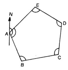
Method of traversing
-
Included angle method
-
Deflection angle method
-
Fast angle (or magnetic bearing method)
Errors in theodolite
Instrumental errors
-
Non adjustment of plate bubble
-
Line of collimation not being perpendicular to horizontal axis
-
Horizontal axis not being perpendicular to vertical axis
-
Line of collimation not being parallel to axis of telescope
-
Eccentricity of inner and outer axes
-
Graduation not being uniform
-
Verniers being eccentric
Personal errors
Natural errors
-
High temperature causes error due to irregular refraction.
-
High winds cause vibration in the instrument, and this may lead to wrong readings on verniers
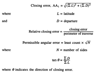
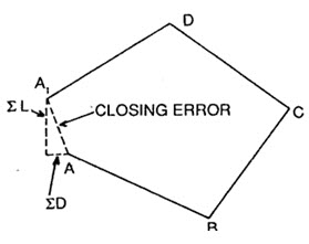
Closing Error
Last modified: Friday, 1 November 2013, 9:08 AM