Site pages
Current course
Participants
General
Module 1. Introduction to by-products and waste ge...
Module 2. Waste management concepts
Module 3. Direct combustion of solid waste
Module 4. Thermo-chemical conversion of solid waste
Module 5. Bio-chemical conversion of solid waste
Module 6. Solid waste management
Module 7. Effluent treatment and disposal
Module 8. Presence of typical chemicals
Topic 9
Topic 10
Lesson 7.
Selection of Proper Size
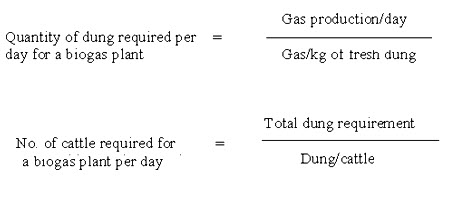
The size (capacity) of biogas plant means the quantity of biogas (in cubic metres or cubic feet) which we can get from it in 24 hours. The selection of proper size of a biogas plant is a very important to meet the required demand of biogas for use. The working of the biogas plant is directly linked with the size. The size of the biogas plant depends upon the number of cattle that a person or an institution would have. There is a minimum requirement of 40 kg of cattle dung for the smallest biogas plant. Normally, 10 to 20 kg of dung is collected from an ordinary cattle. Thus in view of this, it is considered that an average of 15 kg of cattle dung is collected from an animal. From one kg of cattle dung about 0.04 m3 (1.4 ft3) of biogas is collected. There is an requirement of about 0.34 to 0.42 m3 (12 to 15 ft3) of biogas for cooking of food per person per day. Biogas plant can also be operated on human excreta. But there is a requirement of minimum of 70 persons to run a smallest size of biogas size of biogas plant.
Biogas other than cooking food can also be used for running diesel engine and producing light. Table 8.1 shows the requirement of biogas for different purposes. From this Table, the size of the biogas plant can be selected according to the requirement of biogas for a family e.g. if a family having 15-20 family members and this family has to utilize biogas for running diesel engine and producing light other than cooking purpose, then there is a need of minimum 15 m3 size of biogas plant and for this size of biogas plant, the farmer will have to keep 25-30 animals.
Table 8.1 Required quantity of biogas for different purposes
|
Sr. No. |
Purpose |
Size |
Required quantity of biogas (m3/hour) |
|
1. |
Cooking |
5 cm burner 10 cm burner 15 cm burner per person/day |
0.30 0.50 0.64 0.34-0.42 |
|
2. |
Lighting |
100 candle power lamp 1 mantle lamp 2 mantle lamp 3 mantle lamp |
0.13 0.07-0.08 0.14 0.17 |
|
3. |
Diesel engine |
1 H.P. |
0.45-0.51 |
|
4. |
Refrigerator |
Per ft3 capacity |
0.034 |
|
5. |
Incubator |
Per ft3 capacity |
0.014-0.020 |
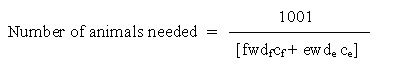 where,
l = annual energy saving needed to recover investment, Rs. per year
w = average weight of animals, kg
f = net fuel replaced with biogas expressible as litre per day per 1000 kg live weight
e = net electricity produced from biogas, kwh per day per 1000 kg live weight.
cf = cost of fuel in Rs. per litre.
ce = cost of electricity in Rs. per kwh
de = Number of days when electricity is produced
df = Number of days when biogas is produced
Selection of proper hydraulic retention time (HRT), digester volume and size of gas holder
1. Hydraulic retention time (HRT)
The atmospheric temperature has great effect on the rate of biogas production in the digester. Low temperature would require more HRT and the digester size would be larger. Different zones of India have been set for having digesters of biogas plants with different hydraulic retention times.
Hydraulic retention time is recommended as below:
i) Plants based on 30 days HRT
This is recommended for states of Andhra Pradesh, Goa, Kerala, Karnataka, Maharashtra, Pondicherry and Tamil Naddu.
ii) Plants based on 40 days HRT
This is recommended for states of Bihar, Gujarat, haryana, Punjab, Jammu area of J & K State, Madhya Pradesh, Orissa, Rajasthan, Uttar Pradesh and West Bengal.
iii) Plants based on 55 days HRT
This is recommended for states of Himachal Pradsh, North-estern states, Sikkim, Kashmir area of J & K state, hilly districts of Uttar pradesh and other hilly areas having long severe winters.
2. Digester volume
Digester volume for different size of biogas plants for different states of India having different HRTs is calculated as below :
Digester volume (V1) for any size of biogas plant having HRT as H is
(Quantity of dung + quantity of water) x H
V1 = ------------------------------------------------------
Density of slurry
Density of slurry = 1100 kg/m3
For example for 1m3 size of biogas plant having HRT as 40 days in Punjab, then V1 is
(25 + 25) x 40
V1 = -------------------- = 1.81 m3
1100
The digester volume should be at least V1. But there are presence of bubbles of gas in the digester, so increase about 10% of the volume of digester.
So digester volume (V) = V1+0.10 V1
Therefore V for biogas plant in Punjab = 1.81 + 0.10 x 1.81 = 1.99 » 2m3
Therefore the volume of digester for any size of biogas plant can be calculated.
3. Size of gas holder
The biogas being produced in the digester is continuously used for sometime in the kitchen for household needs, so size of gas holder be smaller to save cost instead of its total storage. Thus, gas holder of a biogas plant is designed for less capacity as compared to the capacity (size) of biogas plants as follows :-
i.) Community/institutional biogas plants
For these plants, the size of gas holder is recommended from 50% to 70% of the size of biogas plant.
ii) Family size biogas plants
In India kitchen runs 8-12 hours a day, so the size of gas holders for KVIC model and Janta model are recommended as 50% of the capacity (size) of biogas plants whereas for Deenbandhu model, it is recommended as 33% of the size of biogas plants.
Utilization of biogas
Biogas being a very clean and good quality fuel, so it can be utilized for following purposes as:
Biogas for cooking purposes
Biogas provides a clean and efficient fuel for the kitchen, a special biogas burner (stove) other than L.P. burner is used for cooking purposes. It consists of nozzle, an air inlet, mixing chamber and fire sieve element. The nozzle is a hollow tube made of glass, metal, plastic or bamboo. As biogas passes through the nozzle, air is allowed to be drawn into the mixing chamber. For obtaining desired flame temperature, nozzle adjustment is done by trial and error. Biogas stoves normally operates at gas pressure of 7.5 to 9.0 cm of water column. Brightness and combustibility of gas can be maintained as 10:1. Combustibility of gas is maximum when flame is blue. Biogas cannot be burnt on LPG/Natural gas stoves as its nozzle is very small and would permit very little flow of gas.
Biogas can burn if the end of the discharge line is lighted, but this is inefficient and the heat release rate is low due to improper mixing of the air and fuel. The aim of designing a burner is to provide good mixing of air and fuel, to increase-the volumetric heat release rate, the combustion efficiency and heat transfer efficiency. The burner should ensure that the three T’s of combustion are satisfied-temperature, turbulence and time. A good burner will help to produce intense temperature, regulate air supply, regulate the fuel supply and provide mixing of fuel and air. The air to fuel ratio in a burner can be adjusted by cutting the air supply and observing the flame. If incomplete combustion is observed, the air supply should be increased. Excess air should also be avoided as this lowers the combustion temperature and consequently some unburnt gas will flow out defeating the very purpose of excess air.
Biogas stoves should have the following characteristics:
Inlet channels should be smooth to reduce the resistance to flow of gas and air;
Spacing and size of air holder should be sufficient.
Volume in the channel where the gas and air mix should be large enough to allow complete mixing;
Gas jet holes should not be too large but should allow easy passage of the mixed gas and air;
The appliance should be simple, economical and easy to make.
While designing a biogas stove the following characteristics of the biogas are to be considered.
Composition of biogas (generally 60% methane and 40% carbon dioxide).
Pressure of the gas (8.75 - 10 cm water column).
Flame velocity.
The following rules should be observed while designing the biogas stove:
Air must be thoroughly mixed with gas before it reaches the flame ports and should flow near the gas jet, ideally with a venturi (In the absence of sufficient air there is a smell from burning gas).
Total area of the flame ports should be between 8-200 times the area of the gas jet. It may be noted that biogas stoves have large flame port diameters than stoves using LPG.
Distance from the flame ports to the surface of the cooking pot should be between 2.5 cm and 3.0 cm.
Supports for cooking pots should not prevent air from getting to the flame.
To allow cross-lighting from one flame port to the next, the distance between flame ports should not be more than 2.0 cm.
For corrosion-resistance properties, cast iron is better than mild steel.
Given below are the specifications for a 0.45 m3 per hour common biogas stove for domestic use :
Jet size 2.25 mm dia
Area of jet. 3.98 mm2
Flame port size 6.0 mm dia
Number of ports 20
Total area of ports 565 mm2
Ratio of jet area to flame port area 1:142
Length of gas mixing pipe 20 mm
Diameter of gas mixing pipe 20 mm
Sustainability of flame is another important test to adjust the air to fuel ratio. If the flame does not sustain but is put off when the match stick is removed, it can be concluded that either the air supply or the fuel supply is in excess.
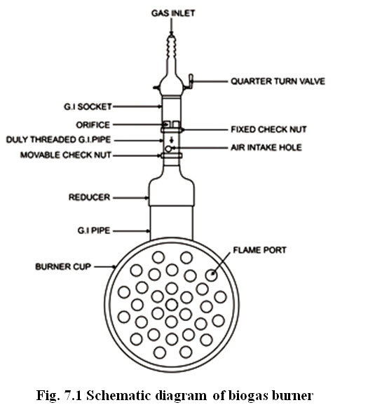
Design of biogas burners
A scheme diagram of the biogas burner is shown in Fig. 11.1. It consists of (i) an orifice for injecting the biogas (ii) an adjustable air port for air entry (iii) a chamber of thorough mixing of gas and air and (iv) ports for exit and burning of gas-air mixture.
The diameter of the orifice can be obtained by the equation.
Q = 3.6 CdA0 [2g (pw/pg)hg]1/2
Where Q = gas flow rate (lit/hr)
Cd = coefficient of discharge (about 0.6)
A0 = area of the orifice (cm2)
g = acceleration due to gravity (981 cm/sec2)
pw = density of water (1000 kg/m3)
pg = density of gas (1.128 kg/m3)
hg = pressure of the gas (cm.w.g.)
For gas pressures of 5-10 cm. w.g., the orifice area per unit flow rate (A0/Q) can be calculated to be about 0.01 mm2 hr/lit. For higher pressures the above formula can be used.
Two 8 mm dia holes with an adjustable check-nut over them should be provided immediately after the orifice for air entry.
The mixing chamber should be about 15-20 cm. long. For high pressures, the length should be increased. The total area of the flame ports should be about 300 times the orifice area for proper flame propagation. Thus the diameter of each hole can be decided once the total number of holes is fixed. A total of 12 holes should be reasonable. The distance of the flame ports to the base of the utensil should be about 2.5 cm.
For cooking purposes, the following types of biogas burners can be used :
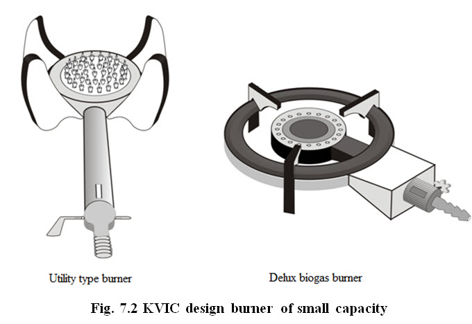
KVIC design burners
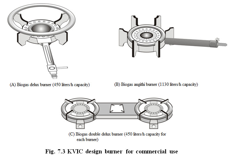
KVIC designed burners (utility type and deluxe biogas burners) are made of cast iron with injectors made of gun metal (Fig. 7.2). These two types of burners consume 0.45 m3 of gas per hour which are adequate for 1-2 member and 5-6 member family, respectively. Initial pressure of gas in gas holder and burners vary from plant to plant. While designing these burners, initial pressure of gas in gas holder is assumed as 8.8 cm water column and in burner, between 7.6 cm and 8.3 cm water column. KVIC has also designed biogas burners for commercial use (for Dhabas, Hostel Messes etc), which are shown in Fig. 7.3.
Tin burners
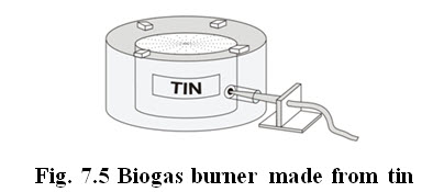
These burners though not very efficient are made of tin to which gas is supplied from base pipelines (Fig. 11.4). Perforations are provided at upper portion of the tin to enable the gas to spurt out for burning. A number of small sized stones are kept outside to facilitate improved air and gas mixing. Tin burner can be embedded inside the earthern ‘chulah’ to suit flat bottomed and round bottomed cooking vessels.
Last modified: Wednesday, 29 January 2014, 11:33 AM