Site pages
Current course
Participants
General
Module 1. Micro-irrigation
Module 2. Drip Irrigation System Design and Instal...
Module 3. Sprinkler Irrigation
Module 4. Fertigation System
Module 5. Quality Assurance & Economic Analysis
Module 6. Automation of Micro Irrigation System
Module 7. Greenhouse/Polyhouse Technology
Lesson 7. Emitter Selection
7.1 Introduction
Emission device selection for drip irrigation systems involves choosing suitable emission device as per the soil and crop need. The type of emission device depends on factors such as the crop to be irrigated, filtration requirements, the need for crop from frost protection, cost and grower preference. Micro sprinklers are considered when a cover crop requires overhead water sprinkling, pest or disease control or for frost protection. Line-source emitters are especially well suited for row crops, although closely spaced point source emitters, bubblers and micro sprinklers can also be used. Bubblers and micro sprinklers will be most viable alternative in situations where water carries large amount of sand and silt filtration requirements are high.
Efficiency of the designed micro-irrigation system depends largely on the emitter selection. The emitters characteristics that affect system efficiency are:
i) Manufacturing characteristics
ii) Hydraulic characteristics and
iii) Operational characteristics.
Further these are elaborated below
-
Variations of emitter discharge due to manufacturing tolerances.
-
Matching of discharge-pressure relationship as per design specifications.
-
Stability of discharge-pressure relationship over a long time.
-
Stability of emitter discharge exponent.
-
Possible range of suitable operating pressures.
-
Loss of pressure on lateral lines caused by the emitters connections.
-
Susceptibility to clogging, siltation, accretion of chemical deposits
The choices of discharge, spacing and the emitter itself are major items in system planning. They are dictated partly by physical data, and also by such factors as emitter placements, type of operation, lateral diameter, and user’s preference. Selection of emitters requires following four steps:
-
Evaluate and choose the general type of emitter that best fits the need of the area to be wetted.
-
According to the system’s required discharge, spacing, and other planning considerations, choose the specific type of emitter needed.
-
Determine the required discharge and pressure head for the average emitter.
-
Determine the allowable variation in sub unit pressure head that will give the desired emission uniformity (Eu).
An ideal set of emitters should have the following attributes:
-
Durability.
-
Low cost.
-
Reliable performance with a relatively low rate of discharge that is reasonably uniform among all emitters within the system despite: variances in tolerances inherent in manufacturing, expected differences in pressure head due to friction loss and elevation, and expected changes in temperature of the water.
-
Relatively large and self-flushing passageways to reduce or prevent clogging.
7.2 Manufacturing Characteristics
Accurate emitter manufacturing is necessary in order to achieve a high degree of system uniformity. However, the complexity of emitter and their individual components make it difficult to maintain precision during production. Changes in production temperature, mold damage and non-uniform mixing of raw materials are some of the factors affecting emitter homogeneity. Elastomeric materials are used to achieve flushing action and pressure compensation in the manufacturing of pressure compensating emitters. These parts are difficult to manufacture with consistent dimensions. In the manufacturing processes, there will be variations in passage size, shape and final finish. Manufacturing variations exist due to the inability to hold constant pressure and temperature during the processes such as molding and welding and inconsistencies in the materials used. Due to these manufacturing variations, any two emitters of the same type from the same box, tested at the same temperature and pressure can have different flow rates. The flow rate in trickle irrigation emitters is small, therefore any variation in the critical dimensions of the emission devices can cause large variation in relative flow rates. Although the absolute magnitude of the variation might be very small. For these reasons, water application uniformity may be greatly affected by the emitter performance. The manufacturing coefficient of variation (CVm) is defined as the statistical coefficient of variation (standard deviation divided by the mean discharge rate) in emitter discharge rates when new emitters of the same type are operated at identical pressures and water temperatures. Under these identical operating conditions, differences in flow rates observed are assumed to be due to variations in emitter components. Manufacturing variation reduces uniformity of water application; therefore choose emitters with low values of Cvm. When comparing emitters with similar flow properties, the highest uniformity will be obtained by selecting the emitter with the smallest manufacturing variation.
7.3 Hydraulic Characteristics
Drip emitters regulate water flow by dissipating the energy of the flow through frictional resistance. Laminar flow emitters regulate water flow by dissipating the energy via friction against the walls of the water passage. They utilize long and narrow flow paths, narrower or longer the passage the more the frictional resistance to the flow. Microtubes and spiral path emitters are examples of laminar flow emission devices. Turbulent flow emitters regulate water flow by dissipating energy in friction against the walls of the water passage and also between the particles themselves during their turbulent movements. Orifice, nozzle emitters, tortuous path emitters and jets or sprayers are typically fully turbulent emitters. The drip tapes that utilize orifices are also turbulent flow devices.
7.4 Operational Characteristics
Emitter must be resistant to extreme conditions in the environment and must maintain physical characteristics over their lifetime in order to have consistent flow rates. Coefficient of manufacturing variation (CV), Emission Uniformity (EU) and emitter flow variation (qvar) are three indexes to determine irrigation uniformity.
7.5 Emitter Spacing, Capacity and Emission Uniformity
Emitter flow theory
Hydraulically, most emitters can be classified as long-path emitters, orifice emitters, vortex emitters, pressure compensating emitters and porous pipe emitters. The hydraulic characteristics of each emitter is directly related to the mode of fluid motion inside the emitter, which is characterized by Reynolds number (Re).
Where V is the emitter flow velocity (m s-1), d is the emitter diameter (m), is the kinematic viscosity (m2 s-1). These flow regimes are characterized as (1) laminar, Re< 2000; (2) unstable, 2000 ≤ Re ≤ 4000; (3) partially turbulent, 4000 ≤ Re ≤ 10,000; and (4) fully turbulent, 10,000 ≤ Re.
Emitter spacing
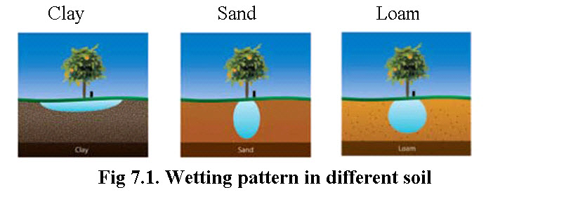
Emitter spacing is a system design characteristic and should be selected taking into account the soil water properties of the site, the specific rooting system of the crop and the climatic characteristics as it affects the extent to which the crop depends on irrigation. For the same application length of time and the same volume of water narrow spacing between drippers on the lateral, renders a narrower and deeper wetting pattern. The width wetted by the drippers increases until adjacent wetted volumes overlap. After the occurrence of overlapping, the majority of the water flow is directed downwards. In case of wide spacing between drippers, it renders a wider and shallower wetting pattern.
Clay soils absorb water slowly and runoff can occur if water is applied too quickly. Clay soils will hold water very well and can stay wet for several days. Drip emitters of 2 L h-1 are selected when planting is done in clay soils and spacing tends to be further apart. Sandy soils absorb water very quickly and runoff usually doesn’t occur. Sandy soils do not hold water very well and can dry out very quickly. Drip emitters of 4 to 8 L h-1 discharge are chosen for planting in sandy soils. The emitter spacing tends to be closer together. Loam soils are an ideal in-between mix of clay and sandy soils. Its absorption rate is greater than that of clay soil but not as fast as sandy soil. When wet, water will move outward and down more evenly. Loam soils will hold water well and dry out at a medium rate. Drip emitters of 2 to 4 L h-1 are selected for planting in loamy soils.
Crops and Planting Geometry
Wide spacing crops: Mango, Citrus, Litchi, Sapota are wide spacing fruits. One or more than one drip emitters of higher discharge ranging from 4 to 8 Lph are used to apply water to meet crop water requirement.
Close spacing crops: Spinach, Coriander, Methi etc. are close growing crops. Micro sprinklers are suitable to irrigate such crops
(Source:www.irrigationdirect.com)
Table 7.1. Typical spacing of emitters of 2 & 4 L h-1 discharge for different soil texture
|
Emitter Capacity |
Type of soil |
Typical Spacing (cm) |
|
4 L h-1 |
Coarse (sand) soil |
60 |
|
Medium soil |
100 |
|
|
Fine (clay) soil |
130 |
|
|
2 L h-1 |
Coarse (sand) soil |
30 |
|
Medium soil |
60 |
|
|
Fine (clay) soil |
100 |
(Source: www.irrigationtutorial.com/drip)
Emitter Capacity
The capacity of drip irrigation emission device may be computed by using equation
where
Q = emission device capacity, L h-1
d = depth of water application, mm
A = area irrigated by the emission device, m2
H = irrigation time, h
Ea = application efficiency
Area Wetted by Emitter
The area wetted by an emission device (A) is computed by following equation
where, A = area irrigated, m2
L = spacing between adjacent plant rows, m
S = spacing between emission points, m
Wp = per cent of cropped area being irrigated;
Ne = number of emission devices at each emission point
The value of Wp varies with crop and growth stage. Wp for wide spacing crops vary between 40 to 60 % and for close spacing crops it varies from 70 to 90 %.
Number of emission devices
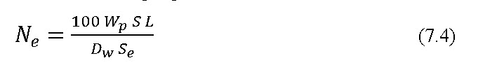
The number emission devices needed for the desired wetting pattern requires information describing the horizontal and vertical movement of water through soil. For single laterals with equally spaced emission points, the following equation estimates the number of emission devices per plant, Ne
![]()
Where,
Dw = maximum diameter of wetted circle formed by a single point source emission device, cm
Se = spacing between the emission devices of an emission point, cm
WP = percent of S times L irrigated
L = spacing between adjacent plant rows (m)
S = spacing between emission points, m
In drip systems with double laterals or Zigzag, pigtail, or multi exit layouts, the Ne is computed with following equation.
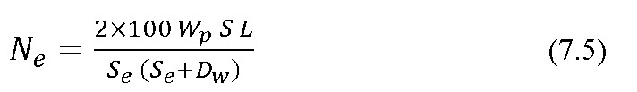
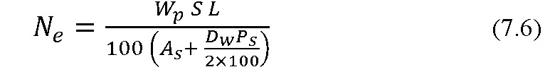

where AS = area wetted by a single micro sprinkler, m2
PS = perimeter of area wetted by micro sprinkler, m
DT = distance of throw, m
Emission uniformity
Several methods have been proposed for assessing the uniformity of water application in irrigation systems. The term emission uniformity has generally been used to describe the uniformity of emitter flow for a drip irrigation unit or subunit. Emission uniformity can be function of: (1) hydraulic variation caused by elevation changes and friction losses along distribution lines and (2) emitter discharge variation at a given operating pressure caused by manufacturing variability, clogging, water temperature changes and aging. Keller and Karmeli (1975) were the first to define an emission uniformity percentage EU for the drip irrigation system as
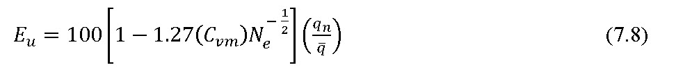
Where Cvm is manufacturer’s coefficient of variation for point source or line source emitters, Ne is the number of point source emitters per emission point (spacing between plants divided by the unit length of lateral line used to calculate or 1, whichever is greater, for line source emitter); is the minimum emitter discharge rate in the system (Lh-1), is the mean emitter discharge rate (Lh-1). The emission uniformity increases as more emitters are added to each plant. Nakayama et al. (1979) developed a Coefficient of design uniformity Cud based on statistical analysis

Admittedly, similarities exist between Eqs. (7.8) and (7.9) since both stress the importance of manufacturing variability and the number of emitters per plant. However, the original derivation of EU was based on the ratio of the discharge rate for the lowest 25% of emitters to the average discharge rate, whereas Cud is based on the discharge rate deviations from the average rate.
Sensitivity to Clogging
The filtration of water used for irrigation is required as drip system operates for the low discharge rates, average diameter of openings for emitter range from 0.0025 to 0.25 mm. These small passageways make all emitters susceptible to clogging. Filtering to remove particles 10 or more times smaller than the emitter passageway is a typical recommendation. Self flushing type emitters require less filtration. Long path emitters, which have the largest passageways for a given flow rate, may still require filtering of even the smaller particles to prevent clogging.
7.6 Pressure Head-Discharge Relationship of Emitter
The relationship between in pressure head and discharge is an important characteristic of emitters. The pressure compensating emitters have a low value of the exponent. However, since they have some physical part that responds to pressure their long range performance requires careful consideration. The compensating emitters usually have a high coefficient of manufacturing variation (Cvm), and their performance may be affected by temperature, material fatigue or both. On undulating terrain, the design of a highly uniform system is usually constrained by the pressure sensitivity of the average emitter. Compensating emitters provide the solution. Emitters of various sizes may be placed along the lateral to meet pressure variations resulting from changes in elevation. In laminar flow emitters which include the long path, low discharge devices the relationship between the discharge and the operating pressure is linear, i.e., doubling the pressure doubles the discharge. Therefore the variations in operating pressure head within the system are often kept to within ± 5 percent of the desired average. In a turbulent flow emitter the change in discharge varies with the square root of the pressure head, i.e., x = 0.5, and the pressure is to be increased four times to double the flow. Therefore, the pressure head in drip irrigation system with turbulent flow emitter is often allowed to vary by ± 10% of the average pressure (US Soil Cons. Service, 1984).
The pressure discharge relationship for emitter is given by

Where,
Q = flow rate, H = operating pressure head, Cd = coefficient of discharge, x = exponent.
Depending upon the experimental values of x, flow regimes can be obtained. Based on the flow regime and exponent x the emitters can be classified (Table 7.2).
Variety of emitters are commercially available, it is convenient to determine discharge directly from manufacturers curves. Some of these curves are available in standard text books and monographs from which Cd and x are computed using equation 7.10. Emitters made from thermoplastic material may vary in discharge depending on the temperature. Therefore, discharge curve should be corrected for temperature. The pressure in the emission device is controlled by various means such as providing i) small openings, ii) long passage ways, iii) vortex chambers, iv) changing the length or cross section of passageways or size of orifice. They are designed to deliver constant discharge for smaller change in pressure. Porous pipe or bi-wall tubing makes very fine jet to apply water and these are buried below the ground surface.
Table 7.2. Emission device classification
|
Flow Regime |
x - Value |
Emitter Type |
|
Variable flow path
|
0.0 0.1 0.2 0.3 |
Pressure compensating |
|
Vortex flow |
0.4 |
Vortex |
|
Fully turbulent flow |
0.5 |
Orifice tortuous |
|
Mostly turbulent flow |
0.6 0.7 0.8 |
Long or spiral path |
|
Mostly laminar flow |
0.9 |
Micro tube |
|
Fully laminar flow |
1.0 |
Capillary |
(Source: www. agridrip.com/page/437645582)
When laterals are laid above the soil surface, the ambient temperature affects the dripper flow rate. As the water temperature increases, water viscosity decreases and the flow rate of the emitter rises. Lateral heating is more pronounced at the distal ends due to the lower flow velocity. As a result, emitters at the end of the lateral may have higher flow rate than emitters at the beginning of the lateral, where as in normal conditions, it is opposite, the flow rate decreases along the lateral due to friction head losses.
Example 7.1 Determine the emission uniformity of a drip system section that uses drip emitter with coefficient of discharge (Cd) = 0.3, exponent (x) = 0.6 and coefficient of variation (Cvm) = 0.06. Two emitters are used for each plant. The average pressure is 100 kPa and minimum pressure is 95 kPa .
Solution:
Given Cd = 0.3, x=0.6
H1 = 95 kPa, H2 = 100 kPa,
Cvm= 0.06, Ne = 2
Equation 7.10, the dicharge Q1 at 95 kPa pressure
\[{{\rm{Q}}_1}{\rm{}}={\rm{}}{{\rm{C}}_{\rm{d}}}{{\rm{H}}^{\rm{x}}}\]
= 0.3 × (95)0.6
= 4.61 Lh-1
For 100 kPa pressure, the discharge
\[{{\rm{Q}}_2} = {C_d}{H^x}\]
= 0.3 × (100)0.6
= 4.75 Lh-1
\[{E_u} = 100\left[ {1 - \frac{{1.27\left( {0.06} \right)}}{{\sqrt 2 }}} \right]\frac{{4.61}}{{4.75}}\]
=100[0.946]*0.97
= 91.7 %
Emission uniformity of the drip system given in the Example 7.1 is in the recommended range. If value of EU is lower than the recommended value the EU could be improved by reducing the difference between Q1 and Q2 (by using larger diameter and/or shorter laterals or by using pressure compensating emitters) or by using an emitter with a lower Cvm.
Emission uniformity of the drip system given in the Example 7.1 is in the recommended range. If value of EU is lower than the recommended value the EU could be improved by reducing the difference between Q1 and Q2 (by using larger diameter and/or shorter laterals or by using pressure compensating emitters) or by using an emitter with a lower Cvm.
References:
-
James, L. G. (1988). Principles of Farm Irrigation System Design, John Wiley an sons Inc, New York
-
Keller, J. and Karmeli, D. (1975). Trickle Irrigation Design. Rain Bird Sprinkler Manufacturing Corporation Glendora, California, U.S.A, 46–49.
-
Nakayama, F.S., Bucks, D.A. and Clements, A.J., (1979). Assessing Trickle Emitter Application Uniformity. Trans. ASAE 22(4): 816-821.
-
Soil Conservation Service. (1984). Procedures for Collecting Soil Samples and Methods of Analysis for Soil Survey. USDA-SCS, Soil Survey Investigations Report No. 1. GPO, Washington, DC.
-
http://www.irrigationtutorial.com/drip
-
http://www.irrigationdirect.com
-
http://www.agridrip.com/page/437645582
Suggested Readings:
-
Michael, A. M. (2010). Irrigation Theory and Practice, Vikas Publishing House Pvt. Ltd. Noida, U.P. India.
-
James, L. G. (1988). Principles of Farm Irrigation System Design, John Wiley and Sons Inc, New York
Last modified: Friday, 17 January 2014, 10:16 AM