Site pages
Current course
Participants
General
Module 1. Micro-irrigation
Module 2. Drip Irrigation System Design and Instal...
Module 3. Sprinkler Irrigation
Module 4. Fertigation System
Module 5. Quality Assurance & Economic Analysis
Module 6. Automation of Micro Irrigation System
Module 7. Greenhouse/Polyhouse Technology
Lesson 9. Pump Selection
All micro-irrigation systems require energy to carry water through the pipe distribution network and discharge it through the sprinklers and drippers.In some instances this energy is provided by gravity as water flows downhill through delivery system. In most irrigation systems, energy is imparted to the water by a pump that in turn receives its energy from either an electric motor or an internal combustion engine. The combination of pump and prime mover (electric motor or engine) is central to the performance of most irrigation systems. Therefore, it is important that both the pump and the prime mover be well-suited and matched to operate the irrigation system.
Wide range of pumps are commercially available forirrigation purposes. Some applications have specialpump requirements, but there are many commonconsiderations in the selection of an appropriatepump. Some of these are listed below:
• Requirement of pressure (or head) and discharge
• Conditionsat suction and pump
• Source of power available
• Cost per unit of powerconsumption
• Capital cost, depreciation and interest charges
• Frequency of operation
• Reliability
• Physical constraints (for example, pump must fit in a limited space such as in borehole)
• Housing of electrical motor and pump further to keep care of water proofing.
9.1 Types of Pumps
Pumps are classified in two main categories, based onhow energy is given to lift water.The two types are:
• Rotodynamic pumps (centrifugal pumps, mixed flow pumps and axial pumps)
• Positive displacement pumps (pistonpumps, and helical-rotorpumps).
The principal requirement for pumping equipment used in commercial micro-irrigation is high efficiency against comparatively high pressures. This requirement usually limits pumps used for spray systems to rotodynamic pumps. Centrifugal pumps are widely used in agriculture andare a good example of the rotodynamic pump group. However, for small systems requiring pump discharge less than 2 Ls-1 positive displacement pumps can be used under certainconditions. These are normally used in fertilizer injection equipment. In irrigation terms, a pumping rate of2 Ls‑1 is a very low flow and would be applicable tonurseries with misting jets, vegetable growers usingdrip irrigation, and domestic irrigation situations.
9.1.1 Rotodynamic Pumps
Rotodynamic pumps have a rotating impeller whichgives energy to the water. The speed and size of theimpeller determine the pressure and the rate of waterflow out of the pump.The two main types of rotodynamic pumps are thevolute pump and the turbine pump.
a) Volute Type Centrifugal Pump
Volute pumps are widely used in irrigation. They areof simple in construction, the only moving parts beingthe impeller and shaft. The impeller is housed in acasing (volute).The volute pump most often used for irrigationpurposes is the (radial-flow) centrifugal pump.It can be installed with the pump shaft in the verticalor horizontal position. Its size is specified by theinternal diameter at the discharge outlet.
The advantages of the centrifugal pump include thefollowing:
• It can be installed above the water surface.
• It can be mounted on skids for rapid removal of water to avoid floods.
• Not being submerged, it is less liable tocorrosion, although most can operate submergedfor short periods without damage.
• It can be installed as a portable unit and used atmore than one pumping site.
• Where its use is applicable, it is easy and simple toinstall.
• It is cheap to maintain.
Where large quantities of water have to be pumpedagainst low heads, mixed-flow volute (MFV) pumpsare used. At low heads, it is possible to get higherefficiencies with MFV pumps than with radialflowcentrifugal pumps. Another advantage is thatthe power requirements (for a given speed) areapproximately constant through the range of head anddischarge.
b) Turbine Pump
Turbine pumps are mixed-flow and radial-flow(centrifugal) pumps which direct water to thedischarge outlet with diffusion vanes. Axial-flowpumps, in which the impeller resembles a ship’s screw,are generally classed with the turbines.Since turbine pumps are most often used for pumpingfrom bores, there is a limit on impeller diameter andthe pressure which can be developed at a given speed.Volute pumps do not have this physical limitation.When high pressures are required from turbinepumps, extra impellers (stages) are added to the pump.Turbine pumps are driven by either a line-shaft or asubmersible electric motor mounted below and closecoupled to the pump.
c) Jet Pumps
Jet pumps are single-stage centrifugal pumps fittedwith a special assembly called an ejector. The ejectorallows the pump to draw water from depths notpossiblewith a conventional centrifugal pump. Thedisadvantage of jet pumps is their very poor efficiencyand discharge when used in high pressure applications.
9.1.2 Positive Displacement Pumps
The positive displacement (or reciprocating pump)consists of a piston (displacer) moving in a cylinderfrom which liquid enters or leaves through a valvearrangement. The positive displacement pump isa low volume, high head pump, and so is not usedextensively in irrigation systems. These pumpsare used, where constant flow is needed such as in drip, fertigation, spray or mistirrigation.
a) Piston Pump
Piston pumps have a horizontal cylinder sealed from both ends with a piston inside. As the piston movesbackwards and forwards, water is drawn in during thesuction stroke and discharged during the compressionstroke. The discharge pulsates because of this needs to be smoothed out using an air chamber in thedelivery line.
b) Helical Rotor Pump
Helical rotor pumps are single screw pumpsconsisting of a rigid screw-like rotor rolling with aslight eccentric motion in a resilient internal rubberlining (stator). The rotor and stator engage so thata constant seal between the two is maintained. Thediameter, pitch and eccentricity of the rotor controlthe pump’s performance.
The characteristic curve for helical rotor pumps is verysteep: small changes in flow result in large changes inpressure.All positive displacement pumps require a pressure reliefvalve at downstream of the pump to protect the mainline.
9.2 Size of Pumping Unit
Pump Performance Parameters
Capacity, head, power, efficiency, required netpositive suction head, and specific speed areparameters that describe a pump’s performance.
Capacity
The capacity of a pump is the amount of waterpumped per unit time. Capacity is also frequentlycalled discharge or flow rate (Q). Inmetric units it is expressed as liters per minute (Lmin-1)or cubic meters per second (m3s-1).
Head
Head is the net work done on a unit weight ofwater by the pump impeller. It is the amount ofenergy added to the water between the suction and delivery sides of the pump. Pumping head is measuredas pressure difference between the discharge andsuction sides of the pump.
Pressure in water can be thought of as beingcaused by a column of the water due to itsweight, exerts a certain pressure on a surface. Thiscolumn of water is called the head and is usuallyexpressed in meters (m) of the liquid.Pressure and head are two different ways ofexpressing the same value. Usually, when the term"pressure" is used it refers to units in kilopascals (kPa), whereas "head" refers to meter’s (m).
Power Requirements
The power imparted to the water by the pump iscalled water horsepower or water power. To calculate water power, theflow rate and the pump head must be known. Water power can be calculated using thefollowing equation:
where
WP = water power, kilowatts
Q = flow rate (pump capacity),m3h-1
H = pump head,m
In any physical process there are always lossesthat must be accounted for. As a result, acertain amount of power is imparted to the water a larger amountof power is imparted to the pump shaft. Thispower is called brake horse power. The efficiency of the pump determines how much more power is requiredat the shaft.
Where, E is the efficiency of the pump expressed as afraction, BP and WP are brake power and waterpower, respectively.
Efficiency
Pump efficiency is the percent of power input tothe pump shaft (the brake power) that is transferredto the water. Since there are losses in the pump, theefficiency of the pump is less than 100% and theamount of energy required to run the pump is greaterthan the actual energy transferred to the water. Theefficiency of the pump can be calculated from thewater horse power (WP) and brake horse power (BP) and is given by
9.3 Power Requirement and Pump Selection
Determination of operating conditions
Before a pump is selected it is necessary todetermine the head (H) and discharge (Q) required for the irrigation system (sprinkler/ drip). The system head versusdischargerelationship is developed for theentire range of operating conditions. Most pumps operate for specific range of head-discharge condition. The selection of pump becomes difficult for satisfying all operation conditions when these existsin wide range of system head discharge variation. Since most pumps are not very efficient over widerange in operating heads, the most prevalentconditions should be determined and a pump thatoperates efficiently over this set of conditions, andcan operate under all other possible conditions,should be selected.
Total dynamic head required by the system
For a given irrigation system a pump mustprovide the required flow rate at the required head(or pressure). The total dynamic head (TDH) curveof the system (Figure 9.1) illustrates the head isrequired to deliver desired flow through the system Fig. 9.1).
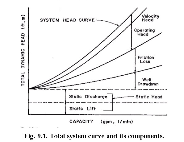
(Source: Haman et. al., 1992)
The pressure required for operating a given sprinkler nozzle or emitter represents only a portion of thetotal dynamic system head. Additional pressure mustbe produced by the pump to lift water from the wellor other water source, to overcome friction losses inthe pipe and other components of the system, and toprovide velocity for the water to flow through thepipe. As a result, the total dynamic head for thesystem is the sum of static head (distance the watermust be lifted), well drawdown, operatingpressure(pressure required at the emitter or sprinkler head),friction head (energy losses) and velocity head (energyrequired for water to flow). Figure 9.1 illustrates thesecomponents of the system TDH. It can be expressedas:
![]()
Where,
Ht = total design head against which pump is working, m
Hn = maximum head required at the main to operate the sprinklers/ drip on the lateral at the required average pressure,m
Hm = maximum friction loss in the main and in suction line, m
Hj = elevation difference between the pump and the junction of the lateral and the main, m
Hs = elevation difference between the pump and junction of the lateral and the main, m
Horsepower requirement of pump
The horsepower requirement of pumping unit is computed by using following equation (Michael, 2010).

Where,
H = total head loss, m
Q = Capacity of drip/ sprinkler irrigation system Ls-1
ηp = Efficiency of pump, fraction
ηm = Efficiency of motor, fraction
System head variations
The total system head will vary with time due tovariations in well drawdown, head loss due to friction, operatingconditions, and static water level. The static water level changes due to seasons. The friction losses will increase with the life of pumping system components.This is due to corrosion or deposits in the pipeand other components. The static lift component ofthe total dynamic head may vary due to fluctuatingwater levels throughout the season, or from year toyear.In some systems there is a periodic change in theoperating head of the system. It may not be possibleto select a pump that is efficient under a wide rangeof system heads. In some cases an additional(booster) pump, in series with a main pump, mayprovide the additional head, when necessary.
Pump Selection
Pump selection is the last step in theirrigation system design process.An irrigation designer estimates field sizes,pipe size and layout, the number of valves, typeof filters and the different types of fittings to be used. All oftheseinformationhelpsto determine the pressure andflow rate required by the pump, and thus finally thepump selection is done.
9.4 Head - Discharge Curve
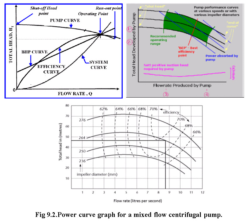
Characteristic curves
A set of four curves known as the pump’s characteristic curve is used to describe the operating properties of a centrifugal pump. These four curves relate head, efficiency, power, and net positive suctionhead required to pump capacity (Figure 9.2). Pumpmanufacturers normally publish a set of characteristiccurves for each pump model they make. Data forthese curves are developed by testing several pumpsof a specific model. The operating properties of apump depend on the geometry and dimensions of thepump’s impeller and casing.
Head Vs Pump Capacity
This curve relates head produced by a pumpto the volume of water pumped per unit time.Generally, the head produced decreases as theamount of water pumped increases. The shape of thecurve varies with pump’s specific speed and impellerdesign. Usually, the highest head is produced at zerodischarge and it is called the shut-off head.
Efficiency Vs Pump Capacity
The efficiency of a pumpsteadily increases to a peak, and then declines as Qincreases further. Efficiency varies between types ofpumps, manufacturers and models.
Brake power Vs pump capacity
The shape of the brake power versus dischargecurve is a function of the head versus discharge andefficiency versus discharge curves. In some cases the highestpower demand is at the lowest discharge rate and itcontinues to decline as the discharge increases. It isimportant to notice that even at zero discharge, whenthe pump is operating against the shut-off head, aninput of energy is needed.
Net Positive Suction Head Required Vs Pump Capacity
One of the curves typically published bymanufacturers is the net positive suction head required (NPSHr) versus capacity (Q). For a typical centrifugal pump the NPSHr steadily increases as Qincreases. To assure that the required energy isavailable, an analysis must be made to determine thenet positive suction head available NPSHa which is a function of the pumping system design.
All pumps come with a head discharge curve graph that shows their operating efficiency at different flow rates and pressures.Most head discharge curve graphs work in meters head for pressure, and cubic meters per hour or litres per minute for flow. It is very important to work in the correct appropriate units. Table 9.1provides conversion of one unit to other required units.
Table 9.1. Pressure conversions and flow conversions for different units
|
Pressure Conversions |
Flow Conversions |
||||
|
Convert from |
To |
Multiply by |
Convert from |
To |
Multiply by |
|
kPa |
Meters head |
0.102 |
L h-1 |
L s-1 |
0.017 |
|
Meters head |
kPa |
9.8 |
L s-1 |
L h-1 |
3600 |
|
kPa |
psi |
0.145 |
m3h-1 |
L h-1 |
1000 |
|
psi |
kPa |
6.9 |
L h-1 |
m3h-1 |
0.001 |
(Source: www. Rainfornet.com/services/pump-training/#System Curve)
Example 9.1: A field has 20 rows of tree with 30 treesper row. One 50 Lh-1microsprinkler is located between each tree, plus one either end of the row. Select the required pumping unit for the system by assuming required data.
The total number of micro sprinklers = 20 (rows) x 31 (micro sprinklers per row)
= 620 micro sprinklers
The required flow rate is calculated bymultiplying the number of emitters by the
output of one sprinkler: 620 x 50 Lh-1 =31,000 Lh-1.
This is the same as 31 m3h-1, 516 L m-1 or 8.6 L s-1.
Consider 200 kPa is emitter operating pressure (frommanufacturers specifications)
& 265 kPais system pressure losses (calculated by adesigner), then
Required Pressure = 200 kPa (emitters) + 265 kPa (system losses) = 465 kPa.
Therefore, we need a pump that can deliver discharge of 31,000 Lh-1at a pressure of 465 kPa. Using this information we can now select the pump to best suit this irrigation system.
The pressure requirement is 465 kPa which is equal to 47.4 m head.
The flow rate requirement is 31,000 Lh-1 which is equal to 8.6 L s-1
Using these figures and the head-discharge curve graph one can check whether this pump will run the irrigation system efficiently? Normally the pump efficiency should be greater than 60%.
Using the head-discharge curve graph locate 47.4 m total head on the vertical axis and draw a horizontal line across the graph. On the horizontal axis locate 8.6 Ls-1discharge and draw a vertical line up. The point at which these two lines intersect shows the efficiency at which the pump will operate under these flow rate and pressure conditions.The pump selected would be the pump with the 264 mm diameter impeller operating at 2900 rpm. This particular pump is expected to be approximately 69% power efficient. This means that 69% of the energy supplied to the pump from the motor is converted to the required pressure and flow.
There is a large range of pumps available in the market with their own set of head-discharge curve graphs. By knowing the pressure and flow rate required to operate the irrigation system effectively, one can compare one pump against another and select the most efficient pump for a given set of condition.
Reference
Michael.A.M. (2010). Irrigation Theory andPractice., Second Edition, Vikas Publishing House PVT. Ltd. Noida, U.P.
Haman, D.Z., Zaxuta, F.S. and Izuno, F.T. (1992).Selection of Centrifugal Pumping Equipment. Extension circular 1048. IFAS.University of Florida, Gainesville, FL 32611.
http://www. Rainfornet.com/services/pump-training/#SystemCurve
Suggested Reading:
James, L. G. (1988). Principles of Farm Irrigation System Design, John Willey & sons, Inc. New York.
Last modified: Saturday, 18 January 2014, 6:20 AM