Site pages
Current course
Participants
General
Module 1. Micro-irrigation
Module 2. Drip Irrigation System Design and Instal...
Module 3. Sprinkler Irrigation
Module 4. Fertigation System
Module 5. Quality Assurance & Economic Analysis
Module 6. Automation of Micro Irrigation System
Module 7. Greenhouse/Polyhouse Technology
Lesson 14. Design of Sprinkler Irrigation System-I
The sprinkler system is selected considering factors such as land topography, cost of land leveling, soil texture, precipitation intensity of sprinkler nozzle, infiltration capacity of the soil, type of crop being irrigated and overall economics of sprinkler system over conventional irrigation system.
14.1 Sprinkler System Layout
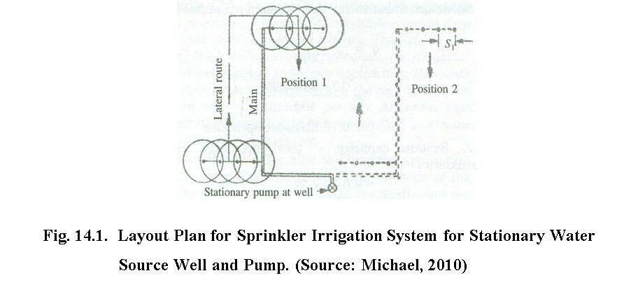
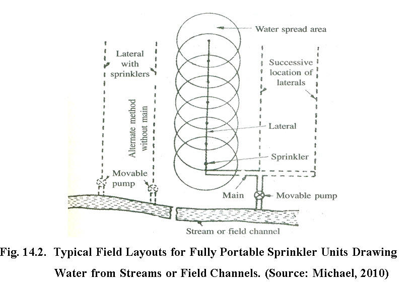
Important factors affecting sprinkler system layout are topography, field shape and the location of the water source. Several alternate layouts are considered to select the best layout after careful analysis and pipe size. Depending on the water source location, the layout of laterals, main and sub mains are decided. The source of water and pumping plant should be located in such a way so as to minimize the pipe length that ultimately affects the pumping cost. In case of drilling a well it should be located in the center of the farm. The layout of the mains will depend on location of well. Fig. 14.1 shows the layout of stationary pump and water source at center of field and laterals are moved to successive position up one side of the main and then down on the other side. Fig. 14.2 shows movable pumping set and portable sprinkler unit drawing water from a field channel running along one edge of the farm. In this system a portable pumping set and sprinkler unit with the lateral extending to the field are used to draw water directly from a stream/ channel and distribute in farm. Another alternative is to have a permanent pumping plant at the source and distribute the water in buried pressure pipelines. These pipelines will usually run down the center of the field so that the outlets offer little hindrance to tillage and other farm operations.
Lateral should be laid across prominent land slopes to minimize the variation of pressure along the lateral. The American Society of Agricultural Engineers (ASAE) recommends that along the lateral pressure variation in set move and solid set systems should not exceed ± 10 per cent of the design lateral pressure. Thus if the design lateral pressure was 300 kPa, the pressure at any sprinkler should not be less than 270 kPa or greater than 330 kPa. When it is necessary to run laterals up and down prominent slopes it is preferable for water to flow down slope rather than up slope. This will compensate the head loss due to friction and also shorten the lateral length for the given pipe size. Laying laterals on uphill should be avoided wherever possible. In case water is required to flow on uphill the length of lateral can be reduced or flow regulators should be used.
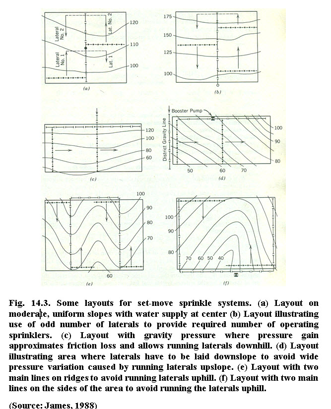
Mains or sub mains are normally run up and down the slopes when laterals run across prominent land slopes. Fig 14.3 shows layouts for set move sprinkler system. When it is necessary to run laterals up and downhill, main lines or sub mains should be located on ridges (Fig 14.c, d, e & f) to avoid laterals that run uphill. Split lateral layouts use set move laterals that may operate on either side of them (Fig 14.3 a, b & e). The labour requirement is reduced by eliminating the need for moving lateral pipes back to the starting point (as is necessary in Figs. 14.3 c & d).
To obtain a reasonable degree of uniformity in the discharge of each sprinkler, the mains should be located in the general direction of the steepest slope, with the laterals at right angles thereto and as close as in practical to the contour. The usual design is based on the lateral being level. If the lateral slopes upgrade appreciably, it is difficult to design laterals for a reasonable length. If its slopes downgrade, the length can be longer than usual, but rarely does the slope remain uniform for each setting.
The general guide lines for set-move sprinkler system are stated below:
i) Mains should be laid up and downhill.
ii) Laterals should be laid across slope or nearly on the contour.
iii) For multiple lateral operations, lateral pipe sizes should be limited to not more than two diameters.
iv) If possible, water supply should be chosen nearest the center of area.
v) Layouts should facilitate minimal lateral movement during the season.
vi) Differences in number of sprinklers operating for various setups should be held to minimum.
vii) Booster pumps should be considered where small portions of field would require high pressure at the pump.
viii) Layout should be modified to apply different rates and amounts of water where soils are greatly different in the design area.
ix) Mainline and sub main layout is keyed to lateral layout.
x) When laterals run across prominent slopes, mainline or sub mains will normally run up and down the slopes.
xi) When it is necessary to run laterals up and down hill, mainlines or sub mains should be located on ridges to avoid laterals that run uphill.
14.2 Parameters for Design of Sprinkler Irrigation System
The basic objective of sprinkler irrigation system is to apply uniform depth of water at predetermined application rate. The sprinkler irrigation system should be designed properly to achieve high irrigation efficiency. The inventory of resources and climatic conditions of the field area are primarily required for the design of sprinkler irrigation system.
14.2.1 Inventory of resources and other parameters
Land: Land is often a major factor in irrigation system design as it influences the selection of sprinkler device, irrigation efficiency, costs of land development, labour requirements, range of possible crops, etc. The major factors of land which have a special bearing on sprinkler irrigation design are: slope, infiltration rate, effective soil depth, texture & structure of soil and size & shape of field.
Water: The source of water supply for sprinkler irrigation can be surface water (river, canal, pond etc.) or ground water (a tube well or open well). Adequate water availability & quality parameters play an important role in the design of sprinkler irrigation system.
Climate: Important climatic data required are solar radiation, temperature, relative humidity, evapotranspiration rate, precipitation or rainfall and wind speed. These climatic parameters are required to estimate peak consumptive use rate as well as total seasonal evapotranspiration of crop(s).
Source of power: Electricity, diesel, solar, wind and biofuels are used to pump water from the source. The selection of pump depends on type of power used to operate pump.
14.2.2 Soil water parameters
Net depth of water application
The depth of water application is the quantity of water, which should be applied during irrigation in order to replenish the water used by the crop during evapotranspiration. The difference between field capacity and permanent wilting point will give the available soil moisture (water holding capacity), which is the total amount of water that the crop can use. Depending on the crop sensitivity to stress, the soil moisture should be allowed to be depleted only partially. For most field crops, a depletion of 60 to 65% of the available moisture is acceptable. This is the moisture that will be easily available to the crop without causing undue stress. The maximum net depth to be applied per irrigation can be calculated, using Equation 14.1.
dnet = (θFC-θWP) x Drz x P ---- (14.1)
where,
dnet = readily available moisture or net depth of water application per irrigation for the selected crop, mm
θFC = soil moisture at field capacity, mm/m
θWP = soil moisture at the permanent wilting point, mm/m
Drz = the depth of soil that the roots exploit effectively (m)
P = the allowable portion of available moisture permitted for depletion by the crop before the next irrigation
In order to express the depth of water in terms of the volume, the area proposed for irrigation is multiplied by depth.
Volume of water to be applied (m3) = 10 x A x d ----(14.2)
where,
A = area proposed for irrigation, ha
d = depth of water application, mm
Example 14.1
A twenty hectare area has medium texture loam soil grown with Wheat crop peak. Daily water use of wheat crop is 6.2 mm day-1. The available soil moisture (θFC – θWP) is 120 mm m-1. The allowable soil moisture depletion is 50%. The crop root zone depth (DRZ) is 0.8 m. Soil infiltration rate is 6 mm h-1. The other climatic data are: average wind speed 10 km h-1. Determine the maximum net depth of water application.
Solution:
Using Equation 14.1, net depth of water application per irrigation for the selected crop is computed as
dnet = 120 x 0.8 x 0.5 = 48 mm
For an area of 20 ha, net application of 9600 m3 (10 x 20 x 48) of water will be required for irrigation to bring the root zone depth of the soil from the 50% allowable depletion level to the field capacity (Equation 14.2).
Irrigation frequency
Irrigation frequency refers to the number of days between irrigations during periods without rainfall. Irrigation frequency depends on crop, soil and climate. After establishing the net depth of water application, the irrigation frequency at peak moisture rate of crop should be determined using the following equation 14.3.
Irrigation frequency (F) = dnet / wu ----(14.3)
Where, F = irrigation frequency, days; dnet = net depth of water application, mm
wu = peak daily water use, mm day-1.
Example 14.2
The peak demand for wheat was estimated as 6.2mm day-1. Using the data available in Example 14.1, determine the irrigation frequency.
Solution:
Irrigation Frequency (F) =48 mm / 6.2 mm/day = 7.7 days
The irrigation system should be designed to provide 48 mm in every 7.7 days. For practical purposes, fractions of days are not used for irrigation frequency. Hence the irrigation frequency in this example is taken as 8 days. The corresponding net depth of dnet of water application
dnet = 6.2x 8 = 49.6 mm
The moisture depletion
= 49.6/(120 x 0.8) = 0.52
The question arises as to whether the irrigation system should apply the dnet in 8, 7, 6, right down to 1 day. This choice will depend on the flexibility the farmer would like to have and his/her willingness to pay the additional cost for different levels of flexibility. If irrigation is to be completed in 1 day, the system becomes idle for the remaining 7 days, and the cost of the system would be exorbitant, since larger sizes of irrigation equipment would be required. On the other hand, for all practical purposes and in order to accommodate the time for cultural practices (spraying etc), it is advisable that irrigation is completed in less than the irrigation frequency. In the case of our example, 7 days irrigation and 1 day without irrigation is considered adequate. The 7 days required to complete one irrigation in the area under consideration is called the irrigation cycle.
Gross depth of water application
The gross depth of water application (dgross) equals the net depth of irrigation divided by the farm irrigation efficiency. It should be noted that farm irrigation efficiency includes possible losses of water from pipe due to leakage or from other sources.
dgross = dnet/E ------(14.4)
Where E = the farm (or unit) irrigation efficiency.
The farm irrigation efficiency of sprinkler systems varies from climate to climate.
Example 14.3
Assuming a moderate climate for the area under consideration and using application efficiency of 75% of sprinkler irrigation, determine the gross depth of irrigation.
dgross =49.6/ 0.75= 66.13 mm
14.2.3 System capacity
The next step is to estimate the system capacity. The system capacity (Q), can be estimated using Equation 14.5 given below
Q = (10 x A x dgross) / (I x Ns x T) -----(14.5)
Where Q = system capacity, m3 h-1; A = area, ha; d = gross depth of water application, mm; I = irrigation cycle, days; Ns = number of shifts per day; T = irrigation time per shift, h.
Example 14.4
The irrigation system operates for 11 hours per shift. Two shifts per day during peak demand is used in each irrigation cycle of 7 days to complete irrigation in 20 ha area. Determine the capacity of irrigation system.
Solution: A=20 ha, dgross=66.13 mm, Ns=2, I = 7 days, T =11 h.
Substituting values in Equation 14.5, the system capacity is
Q = (10 x 20 x 66.13) / (7 x 2 x 11)
Q = 85.88 m3 h-1
14.2.4 Sprinkler systems selection parameters
Sprinkler selection and spacing
Based on specifications furnished by the manufacturers of the equipment the sprinkler system components are selected. The important parameters include in selection are diameter of coverage, pressure available, sprinkler discharge, combination of sprinkler spacing and lateral moves, application rate suiting to soil and wind conditions. The required discharge of an individual sprinkler is a function of the water application rate and the two-way spacing of the sprinklers. The maximum application rate for different types of soils at different land slopes is given in Table 14.1.
Discharge from a sprinkler is computed by
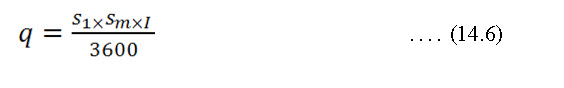
where,
q = required discharge of individual sprinkle, Ls-1
= spacing of sprinklers along the laterals, m
= spacing of laterals along the main, m
I = optimum application rate, mm h-1
Table 14.1 Maximum application rate for different type of soils at different land slopes, cm h-1
|
Soil texture and profile |
0 to 5% slope |
5 to 8 % slope |
8 to 12 % slope |
|
Coarse sandy soils to 2 m |
5.10 |
3.75 |
2.54 |
|
Coarse sandy soils over more compact soils |
3.75 |
2.54 |
1.9 |
|
Light sandy loams to 2 m |
2.54 |
2.03 |
1.5 |
|
Light sandy loams over more compact soil |
1.9 |
1.27 |
1.02 |
|
Silt loam to 2 m |
1.27 |
1.02 |
0.76 |
|
Silt loams over more compact soils |
0.76 |
0.63 |
0.38 |
|
Heavy textured clays or clay loams |
0.38 |
0.25 |
0.20 |
Source: Adapted from SCS (1993).
Example 14.5
A sprinkler system 18 m spacing along the main and 12 m along the laterals is used to irrigate crop grown on coarse sandy soil over more compact soil land slope of 3 per cent. Twenty sprinklers are used to irrigate field. Determine the total system capacity.
Solution:
Discharge from a single sprinkler 
=12 m, = 18 m, I =3.75 cm h-1= 37.5 mm h-1, q = 0.75 L s-1
System capacity (q) = 20 × 0.75 =15 L s-1
Height of sprinkler riser pipes
Sprinklers are located just above the crops to be irrigated and therefore, the height of the risers depends upon the maximum height of the crop. To avoid excessive turbulence in the riser pipes the minimum height of riser is 300 mm for 25 mm diameter and 150 mm for 15 mm to 20 mm diameter. In general, 900 mm long G.I. pipe of 25mm diameter is used.
Sprinkler spacing
The uniformity of water distribution from sprinklers depends on the pressure of water, wind velocity, rotation of sprinklers, spacing and nozzle diameter. The spacing of sprinklers in a lateral and the laterals spacing are adjusted considering all these parameters. Generally at satisfactory desired operating pressure the water distribution beneath sprinkler head accumulate more and depth decreases gradually with distance from the sprinklers.
Normally sprinklers are spaced at 50 per cent of the diameter of the coverage by an individual sprinkler. If there is a wind of considerable speed, the spacing between sprinklers is reduced. Table 14.2 is used to adopt sprinkler spacing under windy condition. This overlap is desired to achieve uniform application on water.
Table: 14.2 Spacing of sprinklers for different wind speed.
|
Sl.No. |
Average wind speed |
Spacing |
|
1 |
No wind |
65% of the water spread area of a sprinkler |
|
2 |
0-6.5 km h-1 |
60% of the water spread area of a sprinkler |
|
3 |
6.5 to 13 km h-1 |
50% of the water spread area of a sprinkler |
|
4 |
Above 13 km h-1 |
30% of the water spread area of a sprinkler |
Source: Michael (2010)
References:
Michael, A. M. (2010). Irrigation Theory and Practice, Vikas Publishing House Pvt. Ltd, Delhi, India, pp.59,592.
James, L. G., (1988). Principles of Farm Irrigation System Design, John Wiley and Sons, Inc., New York, pp.235
Suggested Reading:
- Addink J.W., Keller J, Pair K H, Sneed R.E. and Wolte J.W.(1980) Design and Operation of Sprinkler System. (In Design and Operation of Farm Irrigation System, Chapter 15 Edited by Jensen, M. E.) ASAE Monograph 3, St. Joseph, MI.
Last modified: Saturday, 18 January 2014, 9:52 AM