Site pages
Current course
Participants
General
MODULE 1. PRINCIPLES AND TYPES OF CUTTING MECHANISM
MODULE 2. CONSTRUCTION AND ADJUSTMENT OF SHEAR AND...
MODULE 3. CROP HARVESTING MACHINERY
MODULE 4. FORAGE HARVESTING, CHOPPING AND HANLING ...
MODULE 5. THRESHING MECHANICS, TYPES OF THRESHES, ...
MODULE 6. MAIZE HARVESTING AND SHELLING EQUIPMENT
MODULE 7. ROOT CROP HARVESTING EQUIPMENT
MODULE 8. COTTON PICKING AND SUGARCANE HARVESTING ...
MODULE 9. PRINCIPLES OF FRUIT HARVESTING TOOLS AND...
MODULE 10. HORTICULTURAL TOOLS AND GADGETS
MODULE 11. TESTING OF FARM MACHINES, RELATED TEST ...
MODULE 12. SELECTION AND MANAGEMENT OF FARM MACHIN...
LESSON 6. REAPER AND REAPER BINDERS
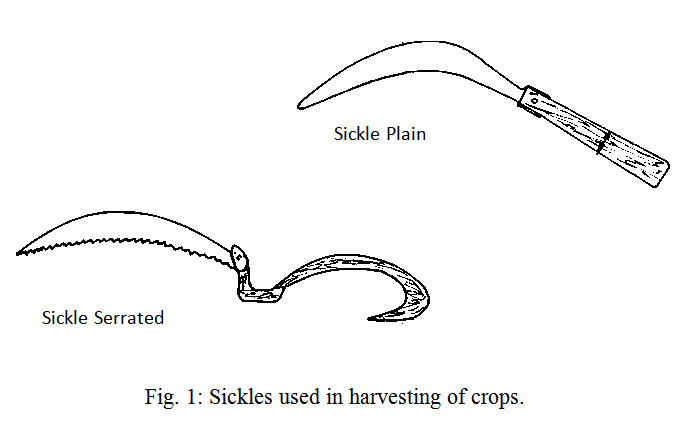
Harvesting equipment may be manually operated, animal-drawn or power operated. Sickle is the most widely used harvesting tool for various crops (Fig. 1). Sickle used may be plain or serrated edged and both types are found effective in cutting plants. Animal drawn reapers have been tried and proved successful on wheat crops. Power operated machines can be reaper, mower, rotary power scythes, forage harvester, binder and conventional combines. A manually operated rotary power scythe (push-cutter) uses a high-speed engine for rotating the cutter blade. A rotary circular disc with plain or serrated edge accomplishes the cutting by impact force. The unit is mounted on the back of the operator, who also activates the cutting rod. The crop is cut and laid in windrows. The output varies between 0.2 to 0.4 ha/day. Tractor front mounted reapers and mowers are also being used for harvesting various crops. It can be powered with power tiller or tractor. Combine harvesters are now becoming increasingly popular in northern India and also in other parts of country. Combines are being used mostly for harvesting crops like wheat, paddy, soybean, sunflower and other crops. Both types of combines viz. self-propelled and tractor operated are common for these crops.
Reaper
Harvesting of cereal crops especially wheat and rice is a serious problem. There is a tremendous crop loss when untimely rain is experienced. Delayed harvesting causes grain shattering due to over maturity. The standing crop in the field can be harvested with the use of reapers. A reaper may be classified as animal-drawn reaper, animal-drawn engine operated reaper, tractor rear mounted PTO operated reaper, power tiller operated or tractor front mounted vertical conveyer type reapers and tractor mounted reaper binder.
Animal-drawn reaper: It consists of a cutter bar of 1.05 m length (Fig. 2). The power to drive the knife bar is given from the ground wheel by means of gear box, crank and connecting rod mechanism. As the machine is pull forward by a pair of bullocks, a reciprocating motion is imparted to the knife bar with a peak cutting velocity of about 100 m/min. The crop is cut due to shearing action. The effective field capacity of machine varies between 0.2-0.3 ha/h.
Fig. 2: Animal-drawn reaper.
Animal-drawn engine operated reaper: It has a cutter bar of 1.35 m length. A 2 hp 4-stroke petrol engine operates the cutter bar. The drive to the cutter bar from engine is given through V belt and gearbox. It can cover 0.2-0.4 ha/h with field efficiency of about 80%.
Power tiller/Tractor front mounted vertical conveyer reaper windrower: A machine called vertical conveyor reaper–cum-windrower can cut the crop and lay it in the form of windrow for easy picking. It consists of a conventional cutter bar assembly, crop row dividers with star wheels, covers, pressure springs and vertical conveyor belts (Fig. 3). Cutter bar is given reciprocating motion by crank wheel. Crop row dividers with star wheels enter the standing crop, help in lifting, gathering and guiding the crop towards the cutter bar. After the crop is cut, held in a vertical position during its passage by means of pressure springs and star wheels. Vertically held crop is then delivered towards right side of the machine in a windrow perpendicular to the direction of movement of machine with the help of lugged conveyor belt. The gearbox and windrower is coupled to the drive shaft of the prime mower. The output shaft transmits power to the shaft driving the lugged flat conveyor belts and a crank is attached at the lower end of the output shaft to operate the cutter bar through connecting rod. The serrated blade cutter bar with standard knife guards is fitted. The top lugged conveyor belt drives the star wheels on the crop row dividers. Pressure springs are fitted below the star wheels between the conveying platforms to keep the cut crop in upright position while it is being conveyed out of the machine. The power in case of power tiller units is transmitted through an intermediate shaft to the gearbox on windrower either by belt or by shaft drive. In tractor mounted models, the power to the gearbox is transmitted from PTO shaft through gearbox by a long shaft running beneath the tractor body to the front and with the help of universal joint and telescopic shaft which is connected to the gearbox. Lowering and raising of reaper is carried out with the help of hydraulic system of a tractor. In case of power tiller the machine pivots on the power tiller wheels. By pushing the handle, the cutter bar can be raised.
A front mounted vertical conveyor reaper is the most common reaper, to harvest wheat and paddy crops. It can also be used for harvesting of soybean and other similar crops. Engine operated reaper (Fig. 4) can be operated with a 5-6 hp engine, whereas, tractor operated reapers (Fig. 5) can be operated with 25-35 hp tractor. Width of cut is about 1.6 m in power tiller reaper, and about 2.05 m in tractor operated reapers. Stroke per min of cutter bar is 1225 and 1550 in case of power tiller and tractor operated reapers, respectively. Power tiller and tractor-front mounted vertical conveyer reaper windrower can cover about 0.2 ha/h and 0.4 ha/h, respectively.
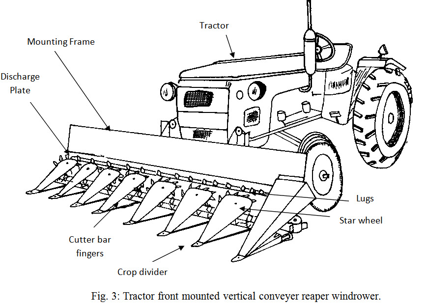
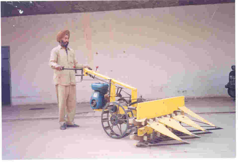
Fig. 4: Self-propelled vertical conveyor reaper-cum-windrower.
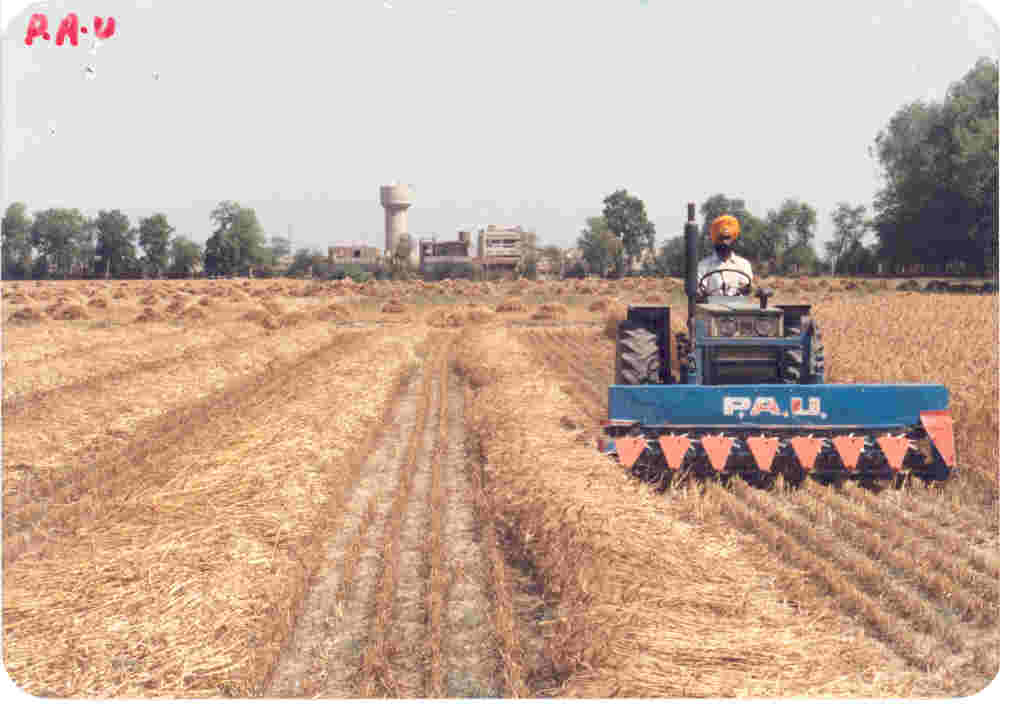
Fig. 5: Tractor front mounted vertical conveyor reaper-cum-windrower.
Tractor rear mounted PTO operated self-raking reaper: The machine carries a cutter bar of 1.5m length, the drive to which is given from PTO of a tractor. It is a side delivery machine in which crop is collected over a platform and is delivered on one side in the form of bound bunches of desired size (Fig. 6). The raking and sweeping of harvested crop is done mechanically. A profile cam controls raking motion. An index lever regulates the movement of cam rollers in such a way that either of first, second, third or fourth rake sweeps out the cut crop laid on the platform. The crop is tied into bundles of desired size manually. It can cover about 3 ha/day with field efficiency of 85%. The grain loss varies between 0.2-3.1percent.
Tractor-rear mounted reaper binder: The machine consists of a cutting, gathering knotting mechanism mounted on a high pressure pipe frame with a 3-point linkage arrangement for hitching at the rear of a tractor. It has a 1.36m long cutter bar and power to various components is given from PTO through v-belts and pulleys. The machine can cover 1.5-2.0 ha/day at a forward speed of 2 km/h. Machine can be used for harvesting wheat and paddy both. Grain losses are 2.2-8.0% for wheat and 1.0-5.0% for paddy.
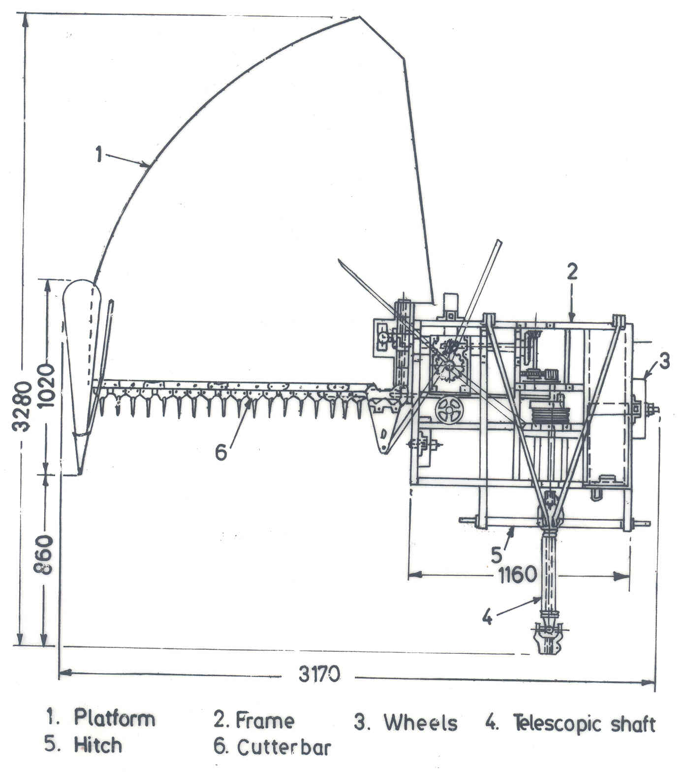
Fig. 6: Schematic view of tractor-rear mounted PTO operated self-raking reaper.
Self-propelled reaper binder
It is suitable for harvesting and making bundle of wheat, paddy and other oilseeds and pulse crops. It is operated by 9 kW diesel engines (Fig. 7). The riding type self–propelled vertical conveyor reaper windrower is powered by a 9 kW, single cylinder, water cooled diesel engine having rated engine speed of 3000 rpm. It is provided with four pneumatic wheels; two driving wheels in the front having agricultural tread pattern tyres and two steering wheels at the rear having automotive tyres. Other systems include clutch, brakes, steering, hydraulics, and power transmission and an operator’s seat is available to make the machine riding type. The harvesting system include crop row dividers, star wheels, standard cutter bar having 76.2 mm pitch of knife section, vertical conveyor belts and wire springs. The effective cutter bar width is 1.2 m. The crop row dividers enter the standing crop and the star wheels guide the crop towards the cutter bar and help in slightly lifting the crop after it is cut, and in turning it at right angle, prior to its conveying by the lugged conveyor belt. The two lugged flat belts convey the cut crop towards the centre of the machine and moves back on a platform where it makes a bundle of about 5 kg each. At the end, the crop is discharged on the ground in the rear. Working capacity of reaper binder is 0.3-0.4 ha/h. Weight of the machine is about 450 kg.
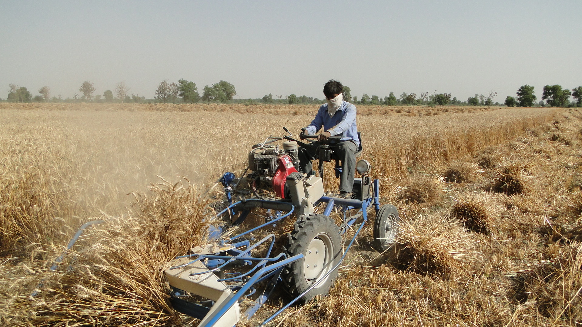
Fig. 7: Self-propelled reaper binder
Reaper problems and adjustments
For proper field efficiency and minimum grain loss, correct field layout and preparation of the field are the most important factors. A swath of about 1.5 m width is required to be first cut all around the field to make passage for the tractor to travel. Alternately, the farmer may want to sow some other crop which could be harvested earlier than the main crop to save the trouble of the hand-harvesting of the initial swath. There are two different modes of turning at the corners as shown in the "Guidelines for proper working of the Reapers." In round turning, the corners are cut in an area to permit the turning of the reaper without pressing or trampling of the stalks by the outer shoe and swath divider. This, however, is not necessary in the poop method of turning. Machine adjustments like the height of the cut and the adjustment of the rakes are made next before starting the operation. As the cutter bar is provided on the right hand side the reaper should be worked in a clockwise direction in the field. The reaper should be run for some distance and the size of the crop-bunches be examined. To make bigger or smaller bunches, the frequency of the sweeping rake needs to be adjusted accordingly. Care should be taken to keep the delivery end of the platform about 15 cm above the ground to facilitate easy dropping of the bunches. The forward speed of the tractor should be carefully selected in accordance with the crop and field conditions. Under Indian field and crop conditions the forward speed is limited to 3 km/h or so. Since the bunches are laid on one side, the passage for the subsequent run of the tractor is cleared automatically. The harvested crop is later tied into bundles of required size manually. The following table gives the common problems in the operation of the reaper-binder which can be remedied through necessary adjustments:
|
Sr. No. |
Part |
Problem |
Adjustment |
|
1. |
Reel |
i) Does not rotate
ii)Improper gathering of crop |
i) Check tension of reel belt. Reel by hand to ensure that the drive pulley key and belt are secured. ii) Adjust height according to height of crop |
|
2. |
Cutter bar |
Unsatisfactory cutting |
i) Reduce forward speed ii) Correct the registration iii) Sharpen the knife sections or replace if worn out. iv) Check drive belt tension. If loose, tighten |
|
3. |
Binding & tying mechanism |
i) Broken or torn twine
ii) Loose or untied knot
iii) Frequent untied bundles
iv) Improper cutting of twine |
i) Remove twine and clean needle eyelet and pliers. Reduce tension on twine under the tension plate through fly-nut ii) Tighten the twine disc with the help of spring loaded screw-bolt provided for the purpose iii) Adjust spring tension and smooth face of pliers by emmary paper. Use twine of uniform thiclmen |
|
4. |
Conveyor |
i) Bundles keep collecting on conveyor ii) Conveyor slackened & bundles not conveyed at regular internal |
i) Check the tension or the v-belt over the conveyor roller pulley.
ii) Tighten the convas conveyor with help of the sum buckles provided |
|
5. |
Bundle size |
|
Increase or decrease the size of bundles by increasing or decreasing the tension of trigger. For this the trigger spring is hooked on to different holes provided |
Reaper problems and numerical
Problem 1:The cutter bar of a mower to the P.T.O of a tractor makes 2000 strokes per minute. The mower has following specifications:
Length of pitman, L = 85 cm
Radius of rotation of crank pin, = 5 cm
Height of the crank shaft centre above the plain of the joint between the cutter and pitman, S = 21 cm
Weight of cutter bar, Wk = 5.3 kg
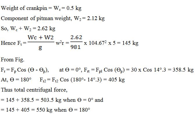
Weight of crankpin, Wc = 0.5 kg
If the pitman weighing 40 kg has its centre of gravity at a distance of 45 cm from the knife end, calculate
a) The inertia force at each end of the stroke
b) Resulting unbalance forces at each end of the stroke
c) Centrifugal force developed on the crank pin at each end of the stroke
Solution :
a. Revolution of the crank per min, N = 1000
Let the weight of the pitman coming on the knife = W1
And weight of the pitman coming on the crank = W2
So, W1 + W1 = weight of pitman
Since the centre of gravity of pitman is 45 cm from the knife end,
W2 = = 2.12 kg and W1 = = 1.88 kg
Fig. no. shows the forces acting on the crankpin and on the knife at any crank angle, Ɵ.
Fig. Forces acting on a reciprocating cutter bar
The inertia force, Fh for the knife and for W1 portion of the pitman weight according to the equation, Fh = rw2…(1)
Where, K = r/L2 – S2
= 5/852 – 212 = 0.06065 and w = = = 104.67 radians/secᶿ
Equation (1) can be used to calculate the inertia, force Fh1and Fh2 at the end of stroke by substituting Ɵ = 0° and Ɵ = 180° respectively.
For Ɵ = 0°, Fh1 = 5 x 104.672 359 kg
For Ɵ = 180°, Fh2 = 5 x 104.672 -0.05 kg
b. Because the pitman and cutter bar are not in the same plane an intermittent vertical force Fv will be introduced at the knife head as shown in Fig. from this figure the resulting unbalanced force at any crank angle can be given by the relationship,
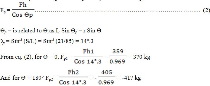
c. At the crank pin, as shown in Fig. the total unbalanced force Fp can be resolved into two components; Fr in the radial direction and tangential component Ft in the tangential direction. In addition to Fr the crank pin will have additional centrifugal force say, Frt due to rotation of the crankpin plus the component of pitman weight.
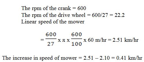
Problem 2: A trailed mower has drive wheels of 60 cm diameter. The crank of the mower makes 600 rpm. When it is hitched to a tractor moving at a constant speed of 2.1 km/hr. if the speed ratio between the crank wheel and land wheel is changed to 27:1, calculate the increase in speed of the mower to maintain same speed of crank.
Solution:
Problem 3: A universal joint is used to transmit power from the power take-off of a tractor to a mower. The two shafts are inclined at 20° and the power take-off shaft rotates at a speed of 540 rpm. Find the extreme angular velocities of the mower shaft and its maximum acceleration.
Solution:

The value of Ɵ for which the acceleration is maximum may be found by differentiating with respect to Ɵ and equating to zero. The resulting expression is, however, very cumbersome. The following approximate equation gives fairly accurate results
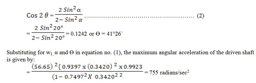
The acceleration is in the opposite direction to the velocity i.e. the mower shaft has maximum retardation, when Ɵ = 41°26´ or 180° + 41°26; and it is in the same direction as the velocity when Ɵ = 138° 34´ or 180° + 138° 34´.
Last modified: Wednesday, 11 September 2013, 10:37 AM