Site pages
Current course
Participants
General
Module 1. Introduction about design and developmen...
Module 2. Study of special design features of trac...
Module 3. Study of basic design parameters for tra...
Module 4. Selection of different mechanical power ...
Module 5. Study of tractor steering and suspension...
Module 6. Design and analysis of tractor hitch sys...
Module 7. Design of a tractor hydraulic system
Module 8. Study of electrical, electronics and gui...
Module 9. Ergonomics, controls and safety features...
Module 10. Tractor testing
Module 11. General revision
Appendices & References
Lesson 9. Mechanics of tractor chassis and stability analysis
1. Introduction
The term 'mechanics' here refers to an analysis of the forces that act on the tractor chassis. The major force is that of gravity and is known as the weight. This is sometimes given in units of mass (kg); in engineering analysis (concerned with statics) all such 'weights' should be converted to force units (kN).
I. Centre of gravity
The centre of gravity is the point at which the whole of the mass and the weight of the tractor may be considered to act. Its location depends on the disposition of the various masses that comprise the tractor. Any analysis of the tractor chassis requires the location of the centre of gravity to be known. It is usually specified in relation to the rear axle as shown by point G in Fig. 9.1.
i. Longitudinal location:
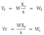
The location of the centre of gravity in the longitudinal (X) direction may be found by measuring the weight on the front (Wf) and rear (Wr) wheels.
Application of the force equilibrium condition gives the tractor weight, W:
W = Wf + Wr ... (9.1)
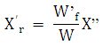
Application of the moment equilibrium condition gives the required longitudinal location, Xr as shown in Fig. 9.1.
For the tractor take moments about O:
![]()
![]() ... (9.2)
... (9.2)
The wheel base (X) between the front and rear axles is usually given in the manufacturer's specification or can be measured directly.For most common rear wheel drive tractors Xr is approximately 30 % of X; this is also the % of the static tractor weight that is on the front wheels.

Fig. 9.1: Location of front and rear wheel location along with CG of a tractor
ii. Vertical location:
The location of the centre of gravity in the vertical (Y) direction is more difficult. The common method is to lift the front (or rear) of the tractor as shown in Fig. 9.2 and measure the weight on the front wheels (W'f) in the raised condition. The following is similar to Barger et. al.,(1952).
Application of the moment equilibrium condition gives the required vertical location, Yg.
For the tractor take moments about O:
The geometry of the positions of the centre of gravity gives:
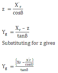 … (9.3)
 ...(9.4)


Fig 9.2: Tractor in raised position
II. Issues in chassis mechanics
Two aspects of the mechanics of the tractor chassis, which are of importance to the performance of the tractor, can be identified:
i. Weight transfer:
For a tractor under dynamic or in operating conditions, the weight on the wheels be different from the static values. These changes are termed as 'weight transfer' or the changes in the vertical longitudinal plane, ie, from front to rear because these have the greatest influence on tractor performance. Weight transfer is a normal outcome of the action of the forces generated on the tractor chassis by the ground and by the implement. It occurs whenever and how the tractor is loaded, including the ‘no’ load case where there is some weight transfer due to the torque on the rear wheels required to propel the tractor against the rolling resistance of all the wheels. It is also normally a desirable outcome because the tractor is designed to take advantage of it by having at least some of the driving wheels at the rear where, for normal forward operation, the increase in rear wheel weight is proportional to the drawbar pull. In reverse gear and in the 'over-run' condition, (the implement pushing the tractor) the forces toward the front of the tractor transfer weight from the rear wheels to the front wheels, a fact which affects the performance of the tractor in this type of work and when braking.
ii. Instability:
Instability occurs when the weight transfer is sufficient to cause the tractor to tip over rearwards. Impending instability (where the front wheels leave the ground and the tractor is on the point of becoming unstable) is considered because it is a limiting case of the weight transfer and hence of tractor operation. It is an undesirable situation because it represents loss of steering control and may lead on directly to actual instability. Such a situation is partly avoided by inherent features of the design of the tractor-implement system and partly by its operation in a way that avoids reaching that condition. Usually the wheels slip before instability occurs. An understanding of the actual process of tipping over in the vertical longitudinal plane which may require more complex dynamic analysis that also includes, inertia of the tractor chassis and of the implement, also the inertia and stiffness of the transmission to the rear wheels.
iii. Analysis and Assumptions
The following analysis of the tractor in the longitudinal, vertical plane is limited to the calculation of wheel weight during steady state operation in normal work and to the prediction of the conditions for impending instability. Although the tractor and implement are moving, the assumption of steady state operation implies that there are no inertia forces; the forces are doing external work but are not causing any acceleration. Hence the principles of statics and the conditions for static equilibrium of rigid bodies can be applied.
Three independent equations of equilibrium can be written:
Sum of the forces in any two perpendicular directions are zero. The two directions usually chosen are those parallel to and perpendicular to the ground surface.
Sum of the moments about any two points in the vertical longitudinal plane are zero. The two points usually chosen are the wheel- ground contact points or the centres of the wheels.
In simple situations it may be sufficient to consider the whole tractor as a rigid body. Where the external forces are known the weights on the wheels can be calculated directly. However it is sometimes convenient to consider the tractor as composed of two rigid bodies. One the drive wheels, rotate about a centre located in the other - the chassis of the tractor. This occurs under the action of the torque acting on them which is internally produced by the engine.
Any such analysis must apply appropriate constraints ie, that the forces and moments on each are equal and opposite. In this analysis and the worked examples, the following simple assumptions are made:
forward motion is uniform; this assumes constant implement forces and no acceleration
Lines of forces on wheels are either tangential or radial or may be resolved as such;
Sinkage and tyre distortion (but not normal tyre deflection) are neglected
Tractor is symmetrical about the longitudinal vertical plane; all the forces and moments may be considered to act in this plane
Other forces, such as the change in position of the fuel and oil in the tractor on sloping ground, air resistance and other minor forces are neglected
1) Weight Transfer
Consider rear wheel drive tractor on a slope as shown in Fig. 9.3.

Fig. 9.3: Tractor for weight transfer analysis
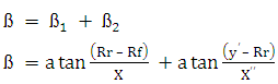
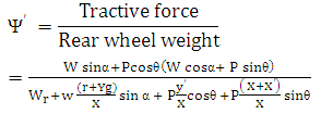
The implement force P acts through the point (x', y') at an angle Ф to the ground surface.
For the tractor, take moments about C:
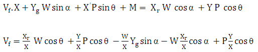 ... (9.5)
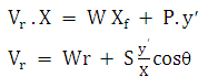
For the wheels, take moments about C: M = H. r
Resolve parallel to the slope: H = ![]()
Substitute for M and H above: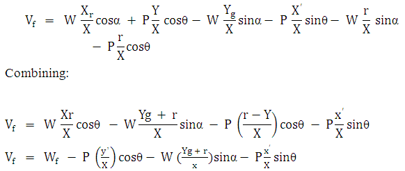 ...(9.6)
Similarly weight on the rear wheels (Vr) perpendicular to the slope is given by:
![]() ...(9.7)
...(9.7)
The terms in Equations can be identified as follows:
Wf, Wr are the static weight on the wheels when the tractor is on the slope
![]() : The moment effect of the weight component down the slope, decreasing the front wheel weight and increasing the rear.
: The moment effect of the weight component down the slope, decreasing the front wheel weight and increasing the rear.
![]() : The moment effect of the implement force component down the slope, decreasing the front wheel weight and increasing the rear.
: The moment effect of the implement force component down the slope, decreasing the front wheel weight and increasing the rear.
![]() : The moment effect of the implement force component perpendicular to the slope, decreasing the front wheel weight.
: The moment effect of the implement force component perpendicular to the slope, decreasing the front wheel weight.
![]() : The direct ( P SINΘ) and the moment effect
: The direct ( P SINΘ) and the moment effect ![]() of the implement force component perpendicular to the slope, increasing the rear wheel weight.
of the implement force component perpendicular to the slope, increasing the rear wheel weight.
Referring to the Equations, moment effect of the component of the drawbar pull down the slope ![]() has two effects:
has two effects:
![]() increases and decreases with moment arm y
increases and decreases with moment arm y
![]() decreases and increases with moment arm r
decreases and increases with moment arm r
The net effect of ![]() is therefore the difference between these two, i.e.,
is therefore the difference between these two, i.e.,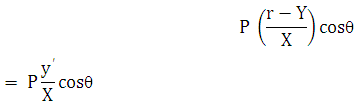
This fact gives rise to the idea that if the drawbar pull acts below the rear axle, its moment, ![]() increases Vf and holds the front of the tractor down. While this is true, it omits the more important, unrecognised aspect that a usually larger moment,
increases Vf and holds the front of the tractor down. While this is true, it omits the more important, unrecognised aspect that a usually larger moment, ![]() tends to decrease the weight on the front wheels.
tends to decrease the weight on the front wheels.
The following special cases are of interest:
1. If y' increases, i.e., the point of action (i.e., the drawbar) is raised, Y decreases and the weight transfer, ![]() increases; the tractor may reach the condition of impending instability when Vf = 0
increases; the tractor may reach the condition of impending instability when Vf = 0
2. If y' = 0, the point of action (the drawbar) is at ground level, Y = r; there is no weight transfer due to P.
3. If y' is negative, the point of action is below ground level (i.e., as is possible with a three point linkage or with the drawbar in a trench), Y is greater than r, the term ![]() becomes positive and negative ie, weight is transferred from the rear to the front wheels.
becomes positive and negative ie, weight is transferred from the rear to the front wheels.
4. If ![]() = 0, ie, the implement force is parallel to the ground
= 0, ie, the implement force is parallel to the ground
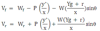
5. ![]() i.e., the ground is horizontal
i.e., the ground is horizontal
6. If also, P = 0, ie, there is no implement force
2) Weight Transfer with Rolling Resistance:
The above analysis neglects any effect of rolling resistance. However, this can be included by introducing force acting along the slope (opposite the direction of motion) as a further force to be overcome by the tractor.
The rolling resistance may be expressed in terms of a coefficient ( ρ ) as
![]()
Here the weight will be the wheel weights perpendicular to the slope, ie, Vf and Vr as given in by equations above. The rolling resistance for the tractor may be estimated by combining the effect on the front andrear wheels by considering a coefficient for the tractor as a whole.
![]()
The total tractive force
![]() ... (9.8)
... (9.8)
Tractive force required (for a rear wheel drive tractor) in terms of the gross tractive coefficient.
 .... (9.9)
3) Weight Transfer with Different Hitching Systems:
Considering the three common hitching systems, evaluation with respect to weight transfer can be donei.e., the increase in the weight on the rear wheels as a result of the implement forces. This analysis does not take into account the weight of the implement, which is more significant for the mounted and semi-mounted systems than for the trailed. However, it provides a valid comparison of the relative advantages of weight transfer of the three systems on the basis of the soil forces and of the conditions under which these advantages will be achieved.
Different type of hitch systems for a tractor are:
(i) Trailed on its own wheels
(ii) Semi-mounted on the lower links of the tractor and a rear wheel
(ii) Fully mounted on the three-point linkage.
In order to compare them it is necessary to determine the dynamic weight on the front and rear wheels of thetractor for each system; the same soil force S, acting at an angle to the ground surface as shown, is assumedfor each.
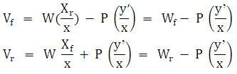
(I) Trailed type hitch system
Tractor with trailed type hitch system is shown in Fig. 9.4.
Resolving horizontally:
P = S cos ![]()
Moments about Q for the tractor:
 …(9.10)
And
![]() ...(9.11)
...(9.11)
Weight transfer will occur if Vr> Wr ie, if y' is positive, ie, if the drawbar is above ground level; it will be increased by increasing the drawbar height, y'.

Fig. 9.4: Tractor with trailed type hitch system
(II) Semi-mounted type hitch system
Tractor with semi mounted hitch system is shown in Fig. 9.5.
Resolving horizontally:
P = S cos ![]()
The dynamic weight T on the tractor drawbar is given by moments about A for the cultivator:
![]()
Where b gives the horizontal location of the soil force.
Substituting for P
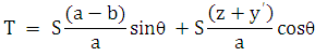
The dynamic weight on the rear wheels is given by moments about Q:
![]()
Substituting for T and P:
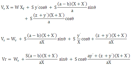
Similarly is given by;
![]() ... (9.12)
... (9.12)
Weight transfer will occur if Vr > Wr which will always occur unless one of the following terms is negative and greater in magnitude than the other.
The first term will be negative if b > a, i.e., the soil force is behind the wheel. The second will be negative if y' is negative (below ground level) and greater than z or z is negative (above ground level) and greater than y'. All of these conditions are unlikely to occur for a semi-mounted implement, hence weight transfer will always occur.

Fig. 9.5: Tractor with semi mounted hitch system
(III) Mounted type Hitch System:
Tractor with mounted hitch system is shown in Fig. 9.6.
The dynamic weights Vr on the rear wheels is given by moments about Q for the tractor / implement system as a whole:
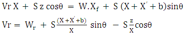 ... (9.13)
The dynamic weight Vf on the front wheels is given by moments about O for the tractor / implement system as a whole:
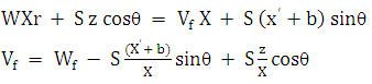 ... (9.14)
Increasing the length of mounted implements (hence increasing b) will increase the weight transfer to the rear wheels due to the direct effect ![]() and the moment effect
and the moment effect ![]() from the front wheels. The limit will be the length and weight that will still allow the tractor to lift the implement without itself tipping up; weights may be added to the front of the tractor to avoid this.
from the front wheels. The limit will be the length and weight that will still allow the tractor to lift the implement without itself tipping up; weights may be added to the front of the tractor to avoid this.
Weight transfer will occur if:
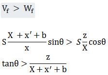
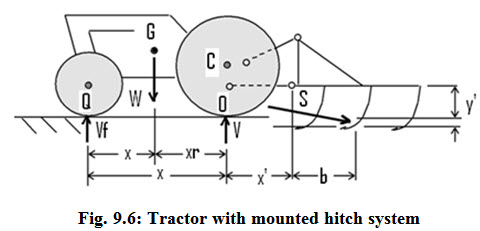
This implies that weight transfer to the rear wheels will occur if the soil force passes above the front wheel /ground contact point.
The above includes the contribution of the vertical component of the soil force (S sinto the rear wheel weight. Another measure associated with weight transfer from the front wheels in the mounted system is the condition that
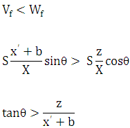
This implies that weight transfer from the front wheels to the rear will occur if the soil force passes above the rear wheel / ground contact point. Further, weight transfer will increase as b increases, ie, the implement gets longer.
Last modified: Saturday, 5 April 2014, 5:36 AM