Site pages
Current course
Participants
General
Module 1: Fundamentals of Reservoir and Farm Ponds
Module 2: Basic Design Aspect of Reservoir and Far...
Module 3: Seepage and Stability Analysis of Reserv...
Module 4: Construction of Reservoir and Farm Ponds
Module 5: Economic Analysis of Farm Pond and Reser...
Module 6: Miscellaneous Aspects on Reservoir and F...
Lesson 32 Other Water Harvesting Structures
32.1 Negarim Micro-catchments
Negarim micro-catchments are diamond shaped basins surrounded by small earth bunds with an infiltration pit in the lowest corner of each. Runoff is collected from within the basin and stored in the infiltration pit. Micro-catchments are mainly used for growing trees or bushes. This technique is appropriate for small scale tree planting in areas with moisture deficit problems. Besides harvesting water for the trees and plants, it simultaneously conserves soil. Negarim micro-catchments are neat and precise, and relatively easy to construct.
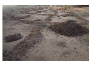
Fig. 32.1. Negarims under construction. (Source: Critchley, 1992)
32.1.1 Background
The word ‘Negarim’ is derived from the Hebrew word for runoff i.e. ‘Neger’. Negarim micro-catchments are the most well known form of all water harvesting systems. Although the first reports of such micro-catchments are from southern Tunisia, the technique has been developed in the Negev desert of Israel.
32.1.2 Technical Details
a. Suitability
Negarim micro-catchments are mainly used for growing tree in arid and semi-arid areas. Here the annual rainfall may be as low as 300-700 mm. The soil should be at least 1.5 m, but preferably 2 m, deep in order to ensure adequate root development and storage of the water harvested. Recommended land slope for such micro-catchments varies from 1 to 5%. The topography of the land need not be necessarily leveled and in case of uneven, a block of micro-catchments should be subdivided.
b. Overall Configuration
Each micro-catchment consists of a catchment area and an infiltration pit (cultivated area). The shape of each unit is normally square, but the appearance from above is of a network of diamond shapes with infiltration pits in the lowest corners (Figure 32.2).
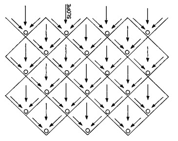
Fig. 32.2. Negarim micro-catchments-field layout.
(Source: http://www.fao.org/docrep/u3160e/u3160e07.htm#TopOfPage)
c. Limitations
Negarim micro-catchments are well suited for hand construction as they cannot easily be mechanized. Once the trees are planted, it is not possible to operate and cultivate with machines between the tree lines.
d. Micro-catchment Size
The area of each unit is either determined on the basis of a calculation of the plant (tree) water requirement or, more usually, an estimate of this. Size of micro-catchments (per unit) normally range between 10 and 100 m2 depending on the species of tree to be planted but larger sizes are also feasible, particularly when more than one tree will be grown within one unit.
e. Design of Bunds
The bund height is primarily dependent on the prevailing ground slope and the selected size of the micro-catchment. It is recommended to construct bunds with a height of at least 25 cm in order to avoid the risk of over-topping and subsequent damage. Where the ground slope exceeds 2%, the bund height near the infiltration pit must be increased. The top of the bund should be at least 25 cm wide and side slopes should be at least in the range of 1:1 in order to reduce soil erosion during rainstorms. Whenever possible, the bunds should be provided with a grass cover since this is the best protection against erosion.
f. Size of Infiltration Pit
The depth of the infiltration pit should not be more than 40 cm in order to avoid water losses through deep percolation and to reduce the workload for excavation. Excavated soil from the pit should be used for construction of the bunds.
g. Quantity of Earthwork
Quantity of earthwork per unit includes only the infiltration pit and two adjacent sides of the catchment, while the other two bunds of the square are included in the micro-catchment above. Additional earthwork is necessary if it is required to have a diversion ditch above.
32.1.3 Maintenance
Maintenance will be required for repair of damages to bunds, which may occur if storms are heavy soon after construction and the bunds are not fully consolidated. The site should be inspected after each significant rainfall.
32.1.4 Husbandry
Tree seedlings of at least 30 cm height should be planted immediately after the first rain of the season as shown in Fig.32.3. It is recommended that two seedlings are planted in each micro-catchment: one in the bottom of the pit (which would survive even in a dry year) and the other on a step at the back of the pit. If both plants survive, the weaker can be removed after the beginning of the second season. For some species, seeds can be planted directly. This eliminates the cost of raising nursery.
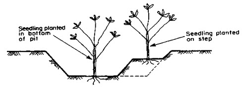
Fig. 32.3. Planting site for seedling.
(Source: http://www.fao.org/docrep/u3160e/u3160e07.htm)
Manure or compost should be applied to the planting pit to improve fertility and water-holding capacity. If grasses and herbs are allowed to develop in the catchment area, the runoff will be reduced to some extent; however, the fodder obtained gives a rapid return to the investment in construction. Regular weeding is necessary in the vicinity of the planting pit.
32.1.5 Socio-economic Considerations
Negarim micro-catchments have been developed in Israel for the production of fruit trees, but even there the returns on investment are not always positive. It is not a cheap technique, bearing in mind that on an average one labour per day is required to build two units, and costs per unit rise considerably as the micro-catchment size increases. It is essential that the costs are balanced against the potential benefits. In the case of multipurpose trees in arid/semi-arid areas, the main benefit will be the soil conservation effect and grass for fodder for several years until the trees become productive. Negarim micro-catchments are suitable for village afforestation blocks and around homesteads where a few open-ended ‘V’ shaped micro-catchments provide shade or support amenity trees.
32.2 Contour Bunds for Trees
32.2.1 Background
Contour bunds for trees are simplified forms of micro-catchments as shown in Fig 32.4. Construction can be mechanized and the technique is therefore suitable for implementation on a larger scale. As its name indicates, the bunds follow the contour, at close spacing, and by provision of small earth ties the system is divided into individual micro-catchments. Whether mechanized or not, this system is more economical than Negarim micro-catchment, particularly for large scale implementation on level land - since less earth has to be moved. Another
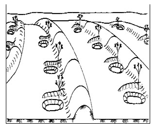
Fig. 32.4. Contour bunds for trees.
(Source: http://www.fao.org/docrep/u3160e/u3160e07.htm)
advantage of contour bunds is their suitability to the cultivation of crops or fodder between the bunds. Like other forms of micro-catchment water harvesting techniques, the yield of runoff is high, and when designed correctly, there is no loss of runoff out of the system. However, contour bunding for tree planting is not yet as common as Negarim micro-catchments.
32.2.2 Technical Details
a. Suitability
Contour bunds for tree planting are recommended for semi-arid and arid areas receiving rainfall up to 200 and 750 mm, respectively. The soils must be at least 1.5 m and preferably 2 m deep to ensure adequate root development and water storage. The prevailing land slope may range between flat to 5%. Above all, the topography of the land should be leveled without rills or gullies.
b. Limitations
Contour bunds are not suitable for undulating or eroded lands as overtopping of excess water with subsequent breakage may occur at low spots.
c. Overall Configuration
The overall layout of contour bunds consists of a series of parallel, or nearly parallel, earth bunds approximately on the contour at a spacing of 5 to 10 m. The bunds are constructed with soil excavated from an adjacent parallel furrow on their upstream side. Small earth ties perpendicular to the bund on the upstream side subdivide the system into micro-catchments. Infiltration pits are excavated in the junction between ties and bunds. A diversion ditch protects the system wherever necessary.
d. Unit Micro-catchment Size
The size of micro-catchment per tree is estimated in the same way as for Negarim micro-catchments. However, the system is more flexible, because the micro-catchment size can be easily altered by adding or removing cross-ties within the fixed spacing of the bunds. Common sizes of micro-catchments are around 10-50 m2 for each tree.
e. Bund and Infiltration Pit Design
Bund heights may vary within the range of 20 - 40 cm depending on the prevailing slope. As bunds are often made by machine, the actual shape of the bund depends on the type of machine; whether for example a disc plough or a motor grader is used. It is recommended that the bund should not be less than 25 cm in height. Base width must be at least 75 cm. The configuration of the furrow upstream of the bund depends on the method of construction.
Bunds should be spaced at either 5 m or 10 m apart. Cross-ties should be at least 2 m long at spacing of 2 to 10 m. The exact size of each micro-catchment is defined based on the spacing between bunds and cross ties. It is recommended to provide 10 m spacing between the bunds on slopes of up to 0.5% and 5 m on steeper slopes. A common size of micro-catchment for multipurpose trees is 25 m2.
It corresponds to 10 m bund spacing with ties at 2.5 m spacing or 5 m bund-spacing with ties at 5 m spacing. Excavated soil from the infiltration pit is used to form the ties. The pit is excavated in the junction of the bund and the cross-tie. A pit size of dimension 80 cm x 80 cm and 40 cm deep is adequate.
32.2.3 Maintenance
Like Negarim micro-catchments, maintenance, in most cases, is limited to repair of damage to bunds early in the initial season. It is essential that any breaches, which are unlikely unless the scheme crosses existing rills, are repaired immediately followed by compaction. Damage is frequently caused if animals invade the plots. Grass should be allowed to develop on the bunds, thus assisting consolidation with their roots.
32.2.4 Husbandry
The majority of the husbandry factors noted under Negarim micro-catchments also apply to this system: there are, however, certain differences. Tree seedlings, of at least 30 cm height, should be planted immediately after the first runoff has been harvested. The seedlings are planted in the space between the infiltration pit and the cross-tie. It is advisable to plant an extra seedling in the bottom of the pit for the eventuality of a very dry year. Manure or compost can be added to the planting pit to improve fertility and water holding capacity.
32.2.5 Socio-economic Factors
Contour bunds for trees are mainly made by machine. The cost of bund construction is relatively low and implementation is faster, especially, where the plots are large and level and the kind of mechanization is well adapted. However, as with all mechanization in areas with limited resources, there is a question mark about future sustainability. Experience has shown that very often the machines come abruptly to a halt when the project itself ends.
32.3 Semi-circular Bunds
32.3.1 Background
Semi-circular bunds refer to earthen embankments in the shape of a semi-circle with the tips of the bunds on the contour. Semi-circular bunds, of varying dimensions, are used mainly for rangeland rehabilitation or fodder production. This technique is also useful for growing trees and shrubs and, in some cases, has been used for growing crops. Depending on the location, and the chosen catchment- cultivated area ratio, it may be a short slope or long slope catchment technique. The examples described here are short slope catchment systems.
Semi-circular bunds are recommended as a quick and easy method of improving rangelands in semi-arid areas. These are more efficient in terms of impounded area to bund volume than other equivalent structures such as trapezoidal bunds etc.
32.3.2 Technical Details
a. Suitability
Semi-circular bunds for rangeland improvement and fodder production are suitable for arid and semi-arid areas receiving up to 200 and 750 mm of rainfall per annum, respectively. The soils should not be too shallow or saline. The land slope should not be greater than 2%. In case of modified bund designs, the land slope can be up to 5%. A level topography is required for semi-circular bunds especially for the type of design ‘a’ shown in Fig. 32.5. The main limitation of semi-circular bunds is that the construction cannot easily be mechanized.
b. Overall Configuration
The two designs of semi-circular bunds discussed here, design ‘a’ and ‘b’ shown in Fig. 32.5; differ in the size of structure and in field layout. Design ‘a’ has bunds with radii of 6 m, and design "b" with radii of 20 m. In both the designs, the semi-circular bunds are constructed in staggered lines with runoff producing catchments between structures.
Design ‘a’ is a short slope catchment technique, and is not designed to use runoff from outside the treated area or to accommodate overflow. Design "b" is also a short slope catchment system, but can accommodate limited runoff from an external source. Overflow occurs around the tips of the bund which are set on the contour.
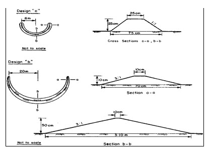
Fig. 32.5. Semi-circular bund dimensions.
(Source: http://www.fao.org/docrep/u3160e/u3160e07.htm)
c. Catchment
Catchment to cultivated area ratio (C: CA ratio) of up to 3:1 are generally recommended for water harvesting systems used for rangeland improvement and fodder production. The reasons for applying low ratios are that already adapted rangeland and fodder plants in semi-arid and arid areas need only a small amount of extra moisture to respond significantly with higher yields. Larger ratios would require bigger and more expensive structures with a higher risk of breaching. Design ‘a’ as described here has low C: CA ratio of only 1.4:1 and does not require any provision for overflow. Design ‘b’ has a higher C: CA ratio of 3:1 and therefore provision for overflow around the tips of the bunds is recommended, though occurrence of overflow is usually rare. A larger C: CA ratio for design ‘b’ is possible but it should not exceed 5:1.
d. Design Variations
Semi-circular bunds can be constructed in a variety of sizes with a range of both radii and bund dimensions. Small radii are common when semi-circular bunds are used for tree growing and production of crops. A recommended radius for these smaller structures is 2 to 3 m with bunds of about 25 cm in height.
32.3.3 Maintenance
Like other earthen structures, the most critical period for semi-circular bunds is when rainstorms occur just after construction because, the bunds are not fully consolidated at this time. In case of any damage, it is recommended for an immediate repair of the structure followed by provision of a diversion ditch if not already constructed. Semi-circular bunds which are used for fodder production normally need repairs of initial breaches only. This is because in the course of time, a dense network of the perennial grasses will protect the bunds against erosion and damage. The situation is different if animals have access into the bunded area and are allowed to graze. In this case, regular inspections and repair of bund damages will be necessary.
32.3.4 Husbandry
It may be possible to allow the already existing vegetation to develop provided it consists of desirable species or perennial rootstocks. In most cases, however, it will be more appropriate to re-seed with seed from outside. Local collection of perennial grass seed from useful species may also be suitable provided the seed is taken from virgin land. Together with grass, trees and shrub seedlings may be planted within the bunds.
32.3.5 Socio-economic Factors
Water harvesting for rangeland improvement and fodder production will mainly be applied in areas where the majority of the inhabitants are agro-pastoralists. In these areas, the concept of improving rangeland on community basis is usually alien. Therefore, it may be difficult to motivate the population to involve and invest voluntarily for implementing and maintaining such a water harvesting system.
Even when this is possible, it is equally important to introduce an appropriate and acceptable rangeland management programme to avoid overgrazing and further degradation of the land. Controlled grazing is also essential to maintain good quality rangeland, and the bunded area must be rested periodically for it to regenerate, so that natural reseeding can take place.
32.4 Contour Ridges for Crops
32.4.1 Background
Contour ridges, sometimes called contour furrows or micro-watersheds, are used for crop production. Thus, it is also known as a micro-catchment technique. Ridges follow the contour at a spacing of usually 1 to 2 m. Runoff is collected from the uncultivated strip between ridges and stored in a furrow just at the upstream of the ridges. Crops are planted on both sides of the furrow. The system is simple to construct either by hand or machine, and can be even less labour intensive than the conventional tilling of a plot.
The yield of runoff from the very short catchment lengths is extremely efficient. When these ridges are designed and constructed correctly, the loss of runoff water out of the system could be prevented completely. Uniform crop growth is another advantage of the system due to the fact that each plant has approximately the same contributing catchment area. However, the contour ridges for crops are not yet a widespread technique.
32.4.2 Technical Details
a. Suitability
Contour ridges for crop production may be recommended for those areas where, the mean annual rainfall is between 350 and 750 mm, soil is suitable for crop production, land slope ranges between flat and 5% and the land topography is leveled. Moreover, it is difficult to construct ridges by hand in areas with heavy and compacted soil. Also areas with rills and undulations are not suitable for contour ridges.
b. Limitations
Contour ridges are limited to areas with relatively high rainfall, as the amount of harvested runoff is comparatively small due to the small catchment area.
c. Overall Configuration
The overall layout consists of parallel or nearly parallel contour ridges approximately on the contour at a spacing of 1 to 2 m (Fig. 32.6). When the furrow is excavated, the dugout soil is placed downstream of the furrow to form a ridge. The furrow collects runoff from the catchment strip between ridges. Small earth-ties in the furrows are provided at frequent intervals to ensure an even storage of runoff. A diversion ditch may be necessary to protect the system against runoff from above.
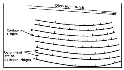
Fig. 32.6.Contour ridges: field layout.
(Source: http://www.fao.org/docrep/u3160e/u3160e07.htm)
d. Catchment: Cultivated Area Ratio
It is a common practice to assume a 50 cm strip with the furrow at its center. Crops are planted within this zone, and use the runoff concentrated in the furrow. Thus, for a typical distance of 1.5 m between ridges, the C: CA ratio is 2:1; that is a catchment strip of 1.0 m and a cultivated strip of half a meter. A distance of 2 m between ridges would give a 3:1 ratio. The C: CA ratio can be adjusted by increasing or decreasing the distance between the ridges.
The calculation of the catchment: cultivated area ratio follows the design model of Chapter 4. In practice, a spacing of 1.5 - 2.0 m between ridges (C: CA ratios of 2:1 and 3:1 respectively) is generally recommended for annual crops in semi-arid areas.
e. Ridge Design
Ridges need only be as high as necessary to prevent overtopping by runoff. As the runoff is harvested only from a small strip between the ridges, a height of 15 -20 cm is sufficient (Fig. 32.7). If bunds are spaced at more than 2 m, the ridge height must be increased.
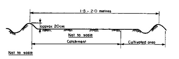
Fig. 32.7.Contour ridge dimensions.
(Source: http://www.fao.org/docrep/u3160e/u3160e07.htm)
f. Earthwork and Labour
Quantities of earthwork for different contour ridge spacing and ridge heights are presented in Table 32.1. It should be noted that the construction of the ridges includes land preparation and so, further cultivation is not required. Where a diversion ditch is necessary, an additional 62.5 m3 of earthwork for each 100 m of length of ditch has to be added.
Table 32.1. Quantities of Earthwork for Contour Ridges
(Source: http://www.fao.org/docrep/u3160e/u3160e07.htm)
|
Ridge spacing (m) |
Ridge & Tie height (cm) |
Earthworks per ha (m3) |
|
1.5 |
15 |
270 |
|
1.5 |
20 |
480 |
|
2.0 |
20 |
360 |
32.4.3 Maintenance
If contour ridges are correctly laid out, it is unlikely that there will be any overtopping and breaching. Nevertheless if breaches do occur, the ridges or ties must be repaired immediately. The uncultivated catchment area between the ridges should be kept free of vegetation to ensure that the optimum amount of runoff flows into the furrows.
At the end of each season the original height of the ridges need to be restored. After two or three seasons, depending on the fertility status of the soils, it may be necessary to move the ridges down the slope by approximately one metre or more, which is likely to result in a fresh supply of nutrients to the plants.
32.4.4 Husbandry
The main crop (usually a cereal) is seeded at the upstream face of the ridge between the top of the ridge and the furrow as shown in Fig. 32.8. In this area, the plants have a greater depth of top soil. An intercrop, usually a legume, may be planted in front of the furrow. In this practice, it is recommended to reduce the plant population of the cereal crop to approximately 65% of the standard for conventional rainfed cultivation. Thus, the moisture available for less number of plants is more during the years of low rainfall. Weeding must be carried out regularly around the plants and within the catchment strip.
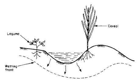
Fig. 32.8.Planting configuration in contour ridges.
(Source: http://www.fao.org/docrep/u3160e/u3160e07.htm)
32.4.5 Socio-economic Factors
Since the contour ridge technique implies a new tillage and planting method compared to conventional cultivation, farmers may be initially reluctant to accept this technique. Demonstration and motivation are therefore very much important. On the other hand, it is one of the simplest and cheapest methods of water harvesting. It can be implemented by the farmer using a hoe, at no or little extra cost. Alternatively it can be mechanized and a variety of implements can be used. When used by a farmer on his own land, the system does not create any conflicts of interest between the executants and the beneficiary.
32.5 Trapezoidal Bunds
32.5.1 Background
Trapezoidal bunds are used to enclose larger areas up to 1 ha and to impound larger amount of runoff which is harvested from an external or long slope catchment. The name is derived from the layout of the structure which is of trapezoidal shape. It consists of a base bund connected to two side bunds or wing walls which extend upstream at an angle of usually 1350. Crops are planted within the enclosed area. Overflow discharges around the tips of the wing walls. The concept is similar to the semi-circular bund technique. However, in this case three sides of a plot are enclosed by bunds while the fourth (upstream) side is left open to allow runoff to enter the field. Simple design and construction; and requirement of minimum maintenance are the main advantages of this technique.
32.5.2 Technical Details
a. Suitability
The trapezoidal bunds are also used for growing crops, trees and grass. Their most common application is for crop production in arid to semi-arid areas with soil of good constructional properties and annual rainfall of 250 - 500 mm. A soil of good constructional property has significant clay content and is non-cracking in nature. The topography of the area within the bunds should be made flat and the allowed land slope is from 0.25% - 1.5%, but most suitable when it is below 0.5%.
b. Limitations
This technique is limited to low ground slopes. Construction of trapezoidal bunds on slopes steeper than 1.5% is technically feasible, but involves large quantities of earthwork.
c. Overall Configuration
Each unit of trapezoidal bund consists of a base bund connected to two wing walls which extend upstream at an angle of 1350. The size of the enclosed area depends on the slope and can vary from 0.1 to 1 ha. Trapezoidal bunds may be constructed as single units or in sets. When several trapezoidal bunds are built in a set, they are arranged in a staggered configuration; units in lower lines intersect overflow from the bunds above. A common distance between the ends of adjacent bunds within the same row is 20 m and a spacing of 30 cm is maintained between the tips of the lower row and the base bunds of the upper row (Fig. 32.9). Of course, the spacing may vary based on the requirement of the site conditions. However, the staggered configuration, as shown in Fig. 32.9, should always be followed. It is not recommended to build more than two rows of trapezoidal bunds since the third or fourth row receives significantly less runoff.
d. Catchment: Cultivated Area (C: CA) Ratio
In this case it is important to determine the necessary catchment size for a required cultivated area. It is sometimes more appropriate to approach the problem the other way round, and determine the area and number of bunds which can be cultivated from an existing catchment.
e. Bund Design
The configuration of the bunds is dependent upon the land slope, and is determined by the designed maximum flood water depth of 40 cm at the base bund. Consequently, as the gradient becomes steeper the wing walls extend to a relatively less distance towards upstream. The greater the slope above 0.5%, the less efficient the model becomes because of increasing earthwork requirements per cultivated area.
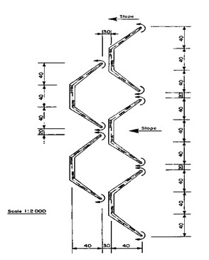
Fig. 32.9. Trapezoidal bunds field layout.
(Source: http://www.fao.org/docrep/u3160e/u3160e07.htm)
32.5.3 Maintenance
Any breach in the bund must be repaired immediately and the earth should be compacted thoroughly. Breaches are often caused by poor construction or because of the production of damaging runoff from the catchment area or both. It are advisable to construct a diversion ditch to protect the repaired bund.
Holes burrowed by rodents can be another cause of breaching. These should be filled in whenever spotted. Allowing natural vegetation to grow on the bunds leads to improved consolidation by the plant roots. Repairs to the wing tips will frequently be needed when overflow occurs. These should be built up immediately and extra stone pitching if required should be provided.
32.5.4 Husbandry
Trapezoidal bunds are normally used for production of annual crops in dry areas. The most common crops are cereals, and of these sorghum and pearl millet are by far the most usual ones. Sorghum is particularly appropriate for such systems because it is tolerant to both drought and waterlogging. In case of trapezoidal bund, the water tends to be unevenly distributed because of the slope, and ponding often occurs near the base bund. Likewise the upper part of the catchment may be relatively dry. Sorghum can tolerate both these situations.
Planting is carried out in the normal way after land preparation in the area within the bund. It is generally suggested to plough parallel to the base bund, so that the small furrows formed by ploughing will accumulate some water locally. In the driest areas planting is sometimes delayed until a runoff event has saturated the soil within the bund, and germination of the seeds or establishment of the tender crop is guaranteed. It is also possible to make use of off-season showers by planting a quick maturing legume, such as cowpea or tepary beans (Phaseolus acutifolius). Another useful technique is to plant cucurbits like gourds or watermelons on the bottom of bund if water ponds deeply.
32.5.5 Socio-economic Factors
It is difficult to generalize about the socio-economic factors concerning trapezoidal bunds, as different variations are found in different circumstances.
As mentioned previously, there are examples of similar structures being used traditionally in Sudan, Africa, where they are often made manually without assistance from any agency and evidently perform well. On the other hand trapezoidal or similar bunds have been constructed in other places using labours under projects food for work or by using heavy machinery. When this has been done without any significant beneficiary commitment, the bunds have been quickly abandoned. The amount of earth moving necessary for trapezoidal bunds indicates that their construction usually requires organized labour or machinery and is beyond the scope of the individual farmer. However, where adequate motivation exists, there is considerable scope for the technique which has a traditional basis and does not require new farming skills.
32.6 Contour Stone Bunds
32.6.1 Background
Contour stone bunds are used to slow down and filter runoff, thereby increasing infiltration and siltation. The water and sediment harvested lead directly to improved crop performance. This technique is well suited to small scale application on farmer's field and, under an adequate supply of stones, can be implemented quickly and cheaply.
Making bunds or merely lines of stones laid in layers is a traditional practice in parts of West Africa, notably in Burkina Faso. Improved construction and alignment along the contour makes the technique considerably more effective. The great advantage of the systems made of stone is that there is no need for spillways, where potentially damaging flows are concentrated. The filtering effect of the semi-permeable barrier along its full length gives a better spread of runoff than earth bunds are able to do. Furthermore, stone bunds require much less maintenance.
Stone bunding techniques for water harvesting (as opposed to stone bunding for hillside terracing, a much more widespread technique) is very much developed in Yatenga Province of Burkina Faso. It has proved to be an effective technique based on its wide spread adaptation and easy in construction.
32.6.2 Technical Details
a. Suitability
Stone bunds for crop production recommended for arid and semi-arid areas receiving mean annual rainfall of 200 – 750 mm. The soil should be fit for crop production with even topography and land slope, preferably, less than 2%.Availability of stones in the nearby locality is a major criterion for stone bunds.
b. Overall Configuration
Stone bunds follow the contour, or the approximate contour, across fields or grazing land. The spacing between bunds ranges normally between 15 and 30 m depending largely on the amount of stone and labour available (Fig. 32.10). There is no need for diversion ditches or provision of spillways.
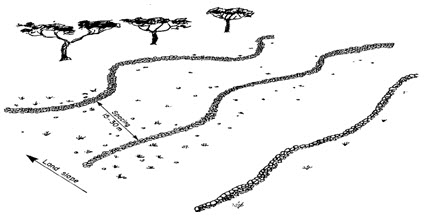
Fig. 32.10.Contour stone bund field layout.
(Source: http://www.fao.org/docrep/u3160e/u3160e07.htm)
c. Catchment: Cultivated Area Ratio
Contour stone bund is a long slope technique relying on an external catchment. Theoretical catchment: cultivated area (C: CA) ratios can be calculated using the formula given in the preceding chapter. Initially it is advisable to be conservative in estimation of areas which can be cultivated from any catchment. The area can be extended either down the slope or upstream in subsequent cropping seasons, if appropriate.
d. Bund Design
Although simple stone lines can be partially effective, an initial minimum bund height of 25 cm is recommended, with a base width of 35 - 40 cm. The bund should be set into a shallow trench, of 5 - 10 cm depth, which helps to prevent undermining by runoff. It is important to note that a mixture of large and small stones is a better for stone bunds. A common error is to use only large stones, which allow runoff to flow freely through the gaps in-between. The bund should be constructed according to the "reverse filter" principle which states that the smaller stones are to be placed upstream of the larger ones to facilitate rapid siltation. Bund spacing of 20 m for slopes less than 1%, and 15 m for slopes between 1 - 2%, respectively, are recommended.
e. Design Variations
Where there is not enough stone readily available, stone lines can be used to form the framework of a system. Grass, or other vegetative material, is then planted immediately behind the lines and forms, over a period of time, a living barrier which has a similar effect to a stone bund. Alternatively, earthen contour bunds can be constructed, with stone spillways set into them.
32.6.3 Maintenance
During heavy runoff events, the stone bunds may be overtopped resulting in dislodgement of some stones. It should be replaced immediately. A more common requirement is to plug any small gaps with small stones or gravel where runoff forms a tunnel through.
Eventually stone bunds silt-up, and their water harvesting efficiency declines. It normally takes three seasons or more to happen, and occurs more rapidly where bunds are wider apart, and on steeper slopes. Bunds should be built up in these circumstances with less tightly packed stones, to reduce siltation, while maintaining the effect of slowing runoff. Alternatively grasses can be planted alongside the bund. The grass supplements the stone bund and effectively increases its height.
32.6.4 Husbandry
Stone bunds in West Africa are often used for rehabilitation of infertile and degraded land. In this context it is recommended that the bunds be supported by a further technique of planting pits. These pits, which are usually about 0.9 m apart, are up to 0.15 m deep and 0.30 m in diameter. Manure is placed in the pits to improve plant growth. The pits also concentrate local runoff which is especially useful at the germination and establishment phase.
As in the case of all cropping systems under water harvesting, an improved standard of general husbandry is important to make use of the extra water harvested. Manuring is very important in fertility management. Apart from it, early weeding is also essential in areas of stone bunding as late weeding is often a constraint to production.
32.6.5 Socio-economic Factors
On-farm stone bunding for crop production is quickly appreciated and adopted by farmers. The techniques involved, including simple surveying, can be easily learned. The amount of labour required is reasonable, and where groups are organized to work in turn on individual member's farms, fields can be transformed in a single day. The benefits of stone bunding are often clearly seen already in the first season and this helps to make the system popular.
Nevertheless, there are some problems encountered in this system. Relatively rich farmers can make use of wage labour to treat their fields, and poor farmers may lag behind. Differing availabilities of stones can lead to inequalities between neighboring areas. Everyone may not be benefitted in the same way.
32.7 Permeable Rock Dam
32.7.1 Background
Permeable rock dams are long, low structures across valley floors which have the simultaneous effect of controlling gulley erosion while causing deposition of silt, and spreading and retaining runoff for improved plant growth (Fig. 32. 11). This is a floodwater harvesting technique.
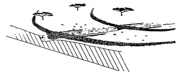
Fig. 32.11.Permeable rock dams. (Source: Critchley et al., 1992)
Permeable rock dams are usually constructed across relatively wide and shallow valleys. Some dams may require central spillways, especially where the water course is incised, but the majority of permeable rock dams will consist of long, low rock walls with level crests along the full length. This causes runoff to spread laterally from the stream course, and, if the dam is overtopped, results in water being distributed evenly along the length of the crest. Wing walls or spreading bunds on the dam should follow the contours away from the centerline of the valley or gully. In addition, contour stone bunds are sometimes used in association with rock dams, especially when the dams are widely spaced. Stone bunds are placed to prevent the overflow from the dam creating a gully downstream of the structure, which could erode back to, and undercut, the dam wall. In general, poor construction of dams at the head of gullies leads to their failure.
Each dam is usually between 50 and 300 m in length. The dam wall is usually 1 m in height within a gully, and between 80 and 150 cm in height elsewhere. The dam wall is also flatter (2:1) on the downstream side than on the upstream side (1:2), to give better stability to the structure when it is full. A shallow trench for the foundation improves stability and reduces the risk of undermining. Large stones are used on the outer wall and smaller stones internally.
32.7.2 Technical Details
a. Dam Design
The main part of the dam wall is usually about 70 cm high although some are as low as 50 cm. However, the central portion of the dam including the spillway (if required) may reach a maximum height of 2 m above the gully floor. The dam wall or spreader can extend up to 1000 m across the widest valley beds, but the lengths normally range from 50 to 300 m. The amount of stone used in the largest structures can be up to 2000 tonnes.
The dam wall is made of loose stone, carefully positioned, with larger boulders forming the framework and smaller stones packed in the middle like a sandwich. The side slopes are usually 3:1 or 2:1 (horizontal: vertical) on the downstream side, and 1:1 or 1:2 on the upstream side. With flatter side slopes, the structure is more stable, but more expensive.
For all soil types it is recommended to set the dam wall in an excavated trench of about 10 cm depth to prevent undermining by runoff waters. In erodible soils, it is advisable to place a layer of gravel, or at least smaller stones, in the trench.
b. Earthwork and Labour
The quantity of stone and the labour requirement for collection, transportation and construction depends on a number of factors and vary widely. The figures were calculated for a rock dam with an average cross section of 0.98 m2 (70 cm high, base width of 280 cm) and a length of 100 m. The vertical interval between dams is assumed to be 0.7 m, which defines the necessary spacing between adjacent dams.
Transport of stones from the collection site to the fields in the valley is the normal method. Considerable labour may be required to collect, and sometimes break, stone. Labour requirements, based on field estimates, are in the range of 0.5 m3 of stone per person per day excluding transport.
32.7.3 Maintenance
The design given above, with its low side slopes and wide base should not require any significant maintenance work provided the described construction method is carefully observed. It will tolerate some overtopping in heavy floods. Nevertheless there may be some stones washed off, which will require replacing, or tunneling of water beneath the bund which will need packing with small stones. No structure in any water harvesting system is entirely maintenance free and all damage, even small, should be repaired as soon as possible to prevent rapid deterioration.
32.7.4 Husbandry
Permeable rock dams improve conditions for plant growth by spreading water, where moisture availability is a limiting factor. In addition, sediment, which will build up behind the bund over the seasons, is rich in nutrients, and this will further improve the crop growth.
This technique is used exclusively for annual crops. In the sandy soils, which do not retain moisture for long, the most common crops are millet and groundnuts. As the soils become heavier, the crops change to sorghum and maize. Where soils are heavy and impermeable, waterlogging would affect most crops, and therefore rice is grown in these zones. Within one series of permeable rock dams, several species of crops may be grown, reflecting the variations in soil and drainage conditions.
32.7.5 Socio-economic Factors
The implementation of permeable rock dams raises several important socio-economic issues. Many of these are rather specific to this technique. This is because permeable rock dams are characterized by:
Large quantities of stone needed
Outside assistance often necessary for transport of stone
Limited number of direct beneficiaries
Construction is often determined by the people rather than the technicians
As the structures cannot be made by individual farmers, it is necessary for others to cooperate in construction. It would be ideal if a village committee can be formed to co-ordinate efforts and discuss the situation of priority sites and beneficiaries. It is unrealistic to expect implementation of such a programme without outside help for transport of stones, which should be provided free of charge to the beneficiaries. Long-term sustainability and replicability of the form of development would best be promoted if beneficiaries could establish revolving funds for the hire or purchase of transport.
32.7.6 Effectiveness of the Technology
Permeable rock dams provide a more effective and popular technique for controlling gully erosion than gabions. Permeable rock dams, in addition to the effective control of gullies, have resulted in considerable increase in crop yield behind the dams. Gullies are rehabilitated by the deposition of silt behind the dams, increasing the depth and quality of the soil immediately behind the dam as a result of the deposition of fertile silt. They have also improved the amount of moisture available for crops. Yields of sorghum from land restored with permeable rock dams range up to 1.9 t/ha compared with a yield of 1 t/ha from equivalent untreated land. Other crops planted behind permeable rock dams include rice (on heavy soils), pearl millet and peanuts.
a. Suitability
This technology is appropriate for regions with less than 700 mm annual rainfall, where gullies are being formed in productive land. It is particularly suited to valley floors with slopes of less than 2%, and where a local supply of stones and the means to transport them is available.
b. Environmental Benefits
The control of gulley formation and the encouragement of silt deposition can have positive effects on a river course and water quality.
c. Advantages
Advantages to be obtained from employing this technology include:
Increased crop production and erosion control as a result of the harvesting and spreading of floodwater
Improved land management as a result of the silting up of gullies with fertile deposits
Enhanced groundwater recharge
Reduced runoff velocities and erosive potentials.
d. Disadvantages
The disadvantages of using this technology include:
High transportation costs
Need for large quantities of stone
Site specificity.
32.8 Water Spreading Bunds
32.8.1 Background
Water spreading bunds are often applied in situations where trapezoidal bunds are not suitable, usually where runoff discharges are high and would damage trapezoidal bunds or where the crops to be grown are susceptible to the temporary waterlogging, which is a characteristic of trapezoidal bunds. The major characteristic of water spreading bunds is that, as their name implies, they are intended to spread water, and not to impound it (Fig. 32.12).
They are usually used to spread floodwater which has either been diverted from a watercourse or has naturally spilled onto the floodplain. The bunds, which are usually made of earth, slow down the flow of floodwater and spread it over the land to be cultivated, thus allowing it to infiltrate.

Fig. 32.12. Flow diversion system with water spreading bunds.
(Source: http://www.fao.org/docrep/u3160e/u3160e07.htm)
35.8.2 Technical Details
a. Suitability
Water spreading bunds are recommended for normally hyper arid or arid areas only receiving mean annual rainfall of 100 – 350 mm. The soil type should be of alluvial fan or floodplain with deep fertile soils. Most suitable slope for water spreading bunds is 1% or less.
b. Topography
The technique of flood water farming using water spreading bunds is very site-specific. The land must be sited close to a ephemeral stream or river or another watercourse, usually on a floodplain with alluvial soils and low slopes. This technique is most appropriate for arid areas where floodwater is the only realistic choice for crop or fodder production.
c. Catchment: Cultivated Area Ratio
The precise calculation of a catchment: cultivated area ratio is not practicable or necessary in the design of most water spreading bunds. The reasons are that the floodwater to be spread is not impounded. Major portion of flood water continues to flow through the system, and furthermore often only part of the stream flow is diverted to the productive area. Thus the quantity of water actually utilized cannot be easily predicted from the catchment size.
d. Bund Design
The land slope has a greater bearing on the design of the bund. Accordingly, its design for slope less than 0.5% and 0.5 to 1% is discussed here.
i) Slopes of less than 0.5%
Where slopes are less than 0.5%, straight bunds are used to spread water. Both ends are left open to allow floodwater to pass around the bunds, which are positioned at 50 m apart. Bunds should overlap in such a manner that the overflow around one should be intercepted by that below it. The uniform cross section of the bunds is recommended to be 60 cm high, 4.1 m base width, and a top width of 50 cm (Fig. 32. 13). This gives stable side slopes of 3:1. A maximum bund length of 100 m is recommended.
ii) Slopes of 0.5% to 1.0%
In this slope range, graded bunds can be used. Bunds, of constant cross-section, are graded along a ground slope of 0.25%. Each successive bund in the series down the slope is graded from different ends. A short wing wall is constructed at 135° to the upper end of each bund to allow interception of the flow around the bund above. This has the effect of further checking the flow. The spacing between bunds depends on the slope of the land. The bund cross section is the same as that recommended for contour bunds on lower slopes. The maximum length of a base bund is recommended to be 100 m.
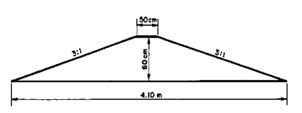
Fig. 32.13.Bund dimensions.
(Source: http://www.fao.org/docrep/u3160e/u3160e07.htm)
32.8.3 Maintenance
As is the case in all water harvesting systems based on earth bunds, breaches are possible in the early stages of the first season, before consolidation has taken place. Thus, there must be planning for repair work whenever necessary and careful inspection after all runoff events. In subsequent seasons the risk of breaching is diminished, when the bunds have consolidated and been allowed to develop vegetation. The vegetation on bunds helps bind the soil together, and reduces direct rainfall damage to the structures. Nevertheless with systems which depend on floodwater, damaging floods will inevitably occur from time to time, and repairs may be needed at any stage.
32.8.4 Husbandry
Water spreading bunds are traditionally used for annual crops, and particularly cereals. Sorghum and millet are the most common. One particular feature of this system, when used in arid areas with erratic rainfall, is that sowing of the crop should be undertaken in response to flooding. The direct contribution by rainfall to growth is often very little. Seeds should be sown into residual moisture after a flood, which gives assurance of germination and early establishment. Further floods will bring the crop to maturity. However if the crop fails from lack of subsequent flooding or if it is buried by silt or sand, as sometimes happens, the cultivator should be prepared to replant. An opportunistic attitude is required. Because water spreading usually takes place on alluvial soils, soil fertility is rarely a constraint to crop production. Weed growth however tends to be more vigorous due to the favourable growing conditions, and thus early weeding is particularly important.
32.8.5 Socio-economic Factors
As the implementation of water spreading systems is a relatively large-scale exercise, consideration has to be given to community organization. One particular problem is that the site of the activity may be distant from the widely scattered homes of the beneficiaries.
A detailed comparison of earthwork and stonework required for various water harvesting systems is presented in Table 32.2.
Table 32.2. Earthwork/stonework for various water harvesting systems
(Source: http://www.fao.org/docrep/u3160e/u3160e07.htm)
|
→ System Name↓ |
Earthwork (m³/ha treated) |
Stonework (m3/ha treated) |
||||||
|
Negarim micro-catchments (trees) |
Contour bunds (trees) |
Semi circular bunds (grass) |
Contour ridges (crops) |
Trapezoidal bunds (crops) |
Water spreading bunds (crops) |
Contour stone bunds (crops) |
Permeable rock dams (crops) |
|
|
Slope % |
(1) |
(2) |
(3) |
(4) |
(5) |
(8) |
(6) |
(7) |
|
0.5 |
500 |
240 |
105 |
480 |
370 |
305 |
40 |
70 |
|
1.0 |
500 |
360 |
105 |
480 |
670 |
455 |
40 |
140 |
|
1.5 |
500 |
360 |
105 |
480 |
970 |
N/R* |
40 |
208 |
|
2.0 |
500 |
360 |
210 |
480 |
N/R* |
N/R* |
55 |
280 |
|
5.0 |
835 |
360 |
210 |
480 |
N/R* |
N/R* |
55 |
N/R* |
* Not recommended
Key words: Water harvesting, earthwork, maintenance
References
http://www.fao.org/docrep/u3160e/u3160e07.htm#5.9 water spreading bunds
Critchley, W., C. Reij, and A. Seznec 1992. Water Harvesting for Plant Production. Volume II: Case Studies and Conclusions for Sub-Saharan Africa. World Bank Technical Paper No. 157, 133 p.
Last modified: Tuesday, 4 February 2014, 11:07 AM