Module 6. Unsteady state heat transfer
Lesson 28
INTENSIFICATION OF HEAT TRANSFER
In solving practical heat-transfer problems, it may be necessary to identify the process in some cases and to reduce it by all possible mean in other. For elementary processes of heat transfer requirement may be fulfilled by utilizing the laws governing the variations in these processes.
The thermal resistance of a wall may be reduced by diminishing its thickness and making it of a material of greater thermal conductivity; heat transfer by convection may be intensified by stirring the fluid and increasing flow velocity; in boiling, intensification can be achieved by stirring the liquid and cleaning the heating surface, and in condensation by properly arranging the cooling surface, cleaning it and increasing the velocity of steam flow; finally, in heat radiation the process is intensified by increasing the emissivity and temperature of the emitting surface. These and other possibilities have been considered rather in detail in studying individual phenomena of heat transfer.
In the cases where heat transfer is the result of individual elementary phenomena occurring simultaneously, intensification of the process becomes complicated and its correct solution may be obtained only by a thorough analysis of the individual conditions of heat transfer.
Such an analysis requires the knowledge of the formulas of the overall heat-transfer coefficient. An investigation of their structure permits evaluation of the effect of individual terms and makes it possible to determine the correct ways and possibilities of solving the given problem.
By way of
illustration, let us consider the formula derived for overall coefficient of
heat transfer through a plane wall. If we neglect the thermal resistance of the
wall, i.e. if we assume ![]() formula
acquires the following form:
formula
acquires the following form:
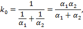
From which it follows that the overall heat-transfer coefficient k is always less than the smallest of heat-transfer coefficient α.
Indeed, let us assume α1 = 40 and α2 = 5,000, then k0 = 39.7 keal/sq m-hr-°C. An increase in α2 practically does not influence k; at α1 = 40 and α2 = 10,000, k0 = 39.8 kcal/m2-hr-°C.
A considerable increase in k0 may be obtained only by changing the smaller of the two heat transfer coefficient, α1 in this particular case. If, for example α2 = 5,000 and α1 = 80, k0 = 78.8 kcal/m2-hr-°C; but if we set α1 = 200, then k0 = 192 kcal/m2-hr-°C.
The dependence k0 = f (α1, α2) it follows that an increase in α1 is accompanied by the relatively rapid growth of k only till α1 and α2 become equal. With a further increase in α1, the rate of k’s increase diminishes, and then practically ceases altogether. Hence if α1 is about α2, heat-transfer may be intensified by increasing each of the heat-transfer coefficients. If α1 is considerable smaller than α2, intensification is attained only by increasing the smaller of the two, α1 in this case.
In the considered analysis, to simplify calculations, the thermal resistance of the wall was assumed to equal zero. This is admissible in practical calculations, but the permissible error should always be known.
Consider a
certain case of heat transfer with

If
we assume that the thermal resistance of the wall is ![]() ,
the value of the overall heat-transfer coefficient will change and be equal to
,
the value of the overall heat-transfer coefficient will change and be equal to
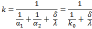
The latter
dependence is presented by the curves where the values ![]() are plotted along the abscissa
are plotted along the abscissa ![]() along
the ordinate, and ko is
chosen as a parameter. It is observed that an increase in the terminal
resistance of the wall is accompanied by a reduction in the overall
heat-transfer coefficient at a rate which increases along with the initial
value of k0.
along
the ordinate, and ko is
chosen as a parameter. It is observed that an increase in the terminal
resistance of the wall is accompanied by a reduction in the overall
heat-transfer coefficient at a rate which increases along with the initial
value of k0.
To illustrate this
conclusion let us solve several numerical problems. Consider a heat exchanger
used to heat water. On the water side α2=5,000 kcal/m2-hr-°C.
The steel wall is of thickness δ = 3 mm and λ = 30 kcal/m2-hr-°C;
hence, ![]()
(a)
If
water is heated by gas and α1=40, then
![]()
and
![]()
(b)
If
water is heated by condensing steam and α1 = 10,000,
![]()
and
![]()
The fins are commonly used for increasing the heat transfer rates from the surfaces whenever it is not possible to increase the rate of heat transfer either by increasing the heat transfer coefficient on the surface or by increasing the temperature difference between the surface and the surroundings fluids. The fins are commonly used on small power developing machines as engines used for scooters and motor – cycles as well as small capacity compressors. They are also used in many refrigerating systems (either in evaporators or condenser) for increasing the heat transfer rates.
An extended surface configuration classed as a straight fin, an annular fin or spine. The terms straight fin is applied to the extended surface attached to a wall which is otherwise plane whereas an annular fin is one, attached circumferentially, to a cylindrical surface. A spine or pin fin is an extended surface of cylindrical or conical shape. These definitions are illustrated.
The circumferential fins of rectangular or triangular profile are commonly used on the engine cylinder of scooters and motor cycles. The pin type fins are used on the condenser of domestic refrigerators.
The knowledge of temperature distribution along the fin is necessary for the proper design of fines. The mathematical analysis for finding out the temperature distribution and heat flow from different types of fins is discussed.
28.1 Heat Transfer through a Rod (Optional)
Consider heat flow through a prismatic rod of cross-section f and parameter U. the rod is kept in a medium at a temperature which we assume to be zero. The temperature of the rod varies only with its length and is a function of length, i.e., ϑ = f (x).The temperature at the base of the rod is ϑ0. Thermal conductivity and the heat-transfer coefficient are known to equal λ and α1.
It is necessary to determine the law governing the change in the temperature along the rod and the amount of heat transferred through the rod in steady-state conditions.
Take an element of length d𝓍 located at the distance 𝓍 from the base of the rod and let us write the equation of heat balance for this element.
It is clear that
![]() ………(a)
………(a)
According to Fourier’s law
![]()
And
![]()
Hence
![]() ………(b)
………(b)
On the other hand,
![]() ………(c)
………(c)
Equating (b) and
(c) and cancelling, we get
![]()
Where
 ………(d)
If α1
does not depend on 𝓍, m = const.
Then, the common integral of the linear differential equation of the second
order has the following form:
![]() ………(e)
………(e)
The value of integration constant C1 and C2 are found from the boundary conditions. These conditions depend on the length of the rod and consequently, will be considered separately.
28.1.1 Infinite rod
At 𝓍
= 0, ϑ = ϑ0 and ϑ0 =C1 + C2;
at 𝓍
= ∞, ϑ=0 and C1e-∞+C2e-∞
= 0, or C1e∞ = 0. The
latter holds only if C1 = 0. Thus
![]() ………(f)
………(f)
Substituting
these values into equation (e), we get
![]()
Hence
ϑ = F (ϑ0, 𝓍,
α1, λ, f, U). Bearing in mind that the exponent m𝓍
is dimensionless, equation may be present in another, dimensionless form,
namely,
![]() ………(g)
………(g)
Therefore, in case of round rod ![]()
The parameter K1 characterizes the change in the temperature along the rod. The mode of temperature variation is different, depending on K1, or rather on the relation between the values determining K1.
The amount of heat lost by the rod to the surroundings is equal to the rate of the heat flow through the base of the rod.
Hence
![]() ………(h)
………(h)
Now ![]() ………(i)
………(i)
Finally
![]()