Module 6. I. C. engine
Lesson 12
CLASSIFICATION AND WORKING OF I.C. ENGINE
12.1 Introduction
Up to now we have studied theoretically about the heat engines. One of the simple designs of a heat engine is a cylinder and piston arrangement such that behind the piston there is a fixed quantity of some working substance, such as air or any other ideal gas. Theoretically, it is a closed system. The fixed mass of gas in engine, undergoes a cyclic change in conditions and during each cycle it takes heat from a heat source, then expands doing work, rejects rest of heat and again compressed to initial conditions using some amount of expansion work.
Net work done by gas in each cycle
= Expansion work−Compression work
= Heat absorbed by gas−Heat rejected by gas
The theoretical cycles, on which the heat engine, is assumed to work, have already been explained as Carnot cycle, Otto cycle, Diesel cycle, Dual cycle etc.
But for making possible an actual heat engine which can continuously supply the useful mechanical work, by using any practically available heat source, there are some practical considerations like what type of heat source can be made available to a heat engine, which can supply heat every time when required in each cycle of engine. Actually the bulk of heat energy can be made available only by igniting some chemical fuel i.e. coal, petrol, diesel or gas etc. Thus the fuel must be burnt for supply of required heat energy continuously in each cycle of engine and, where this fuel should be burnt i.e. outside or inside the engine. The heat engines are broadly classified as external combustion engines and internal combustion engines.
12.2 Classification of Heat Engines
Depending on the place of burning of fuel, i.e. where should it be burnt, there can be two methods and based on that heat engines are broadly divided into two types
i) External Combustion engine
ii) Internal Combustion engine
12.2.1 External combustion (EC) engine
In this case the combustion of fuel takes place outside the engine as in case of steam engines. The heat of combustion of fuel is used to generate high pressure steam which is supplied to the engine through the valve, when it expands and pushes the piston, doing the mechanical work.
Examples of external combustion engine are old steam locomotives, steam turbines (Used in Power Plants) etc.
12.2.2 Internal combustion engine
In this case, the combustion of fuel and mixture take place in the engine itself. Due to the heat of combustion, the pressure and temperature of fuel and mixture increases tremendously and thus high pressure mixture further expands and pushes the piston (or moves a turbine) and does the mechanical work.
Examples are Petrol Engine, diesel Engine, Gas turbine, Jet engines etc.
Now, As in steam engines the steam and in I.C engine the fuel and air are supplied from outside during each cycle of engine and after combustion, smoke in case of I.C. engine has to be removed and fresh air fuel mixture to be sucked in new cycle, these engines are no more a closed system as mass frequently enters and leaves the system. However, I.C. engine work as a closed system during compression and expansion process, when valves are closed.
12.3 Working of an I.C. Engine Based on Air-Cycles
We have come to know that in an I.C Engine, which may be a petrol or diesel engine or a gas turbine engine, the fuel is burnt inside the engine to supply heat energy to it. The working of I.C engine is based on the standard air cycles as discussed before. Theoritically an engine working on these cycles need to be closed system. But practically in an I.C engine, when fuel is burnt in the presence of air, it releases heat energy and change into smoke after burning. The burning content of fuel, which take part in combustion, consume all the oxygen and to burn fuel again, in the next cycle, fresh air is needed. Thus after each cycle, the burnt gases/smoke need to be thrown out and fresh air need to be sucked inside again by automatic operation of exhaust valve and suction valve. Therefore an actual I.C. engine becomes alternatively an open system. The working of an actual I.C. engine differs from that of the theoretical air cycle by two additional processes of suction of fresh charge in to the engine and discharges of burnt gases form the engine. In this way, the complete cycle of an I.C. engine is comprised of the following processes:
i) Suction of fresh charge (Process 5-1)
ii) Compression of fresh charge (Process 1-2)
iii) Heat addition by combustion of fuel (Process 2-3)
iv) Expansion of high pressure burnt gases (Process 3-4)
v) Heat Rejection (Process 4-1)
vi) Exhaust of burst fuel i.e. smoke (Process 1-5)
The working cycle of a 4-stoke Petrol Engine & Diesel Engine is shown in fig 12.1 & 12.2. During the suction and exhaust processes, the engine become an open system and works like a pump as shown below:
Theoretically, the suction & exhaust processes are just opposite to each other. During suction, the work is positive and during exhaust, work is negative and so net work is zero. But practically the fresh air or air-fuel mixture is sucked and combustion material is exhausted through narrow valves, offering resistance to flow of air. Also there is internal friction and difference in temperature inside and outside the engine, so net pumping work is negative, which reduces the positive cyclic work. Thus the net work output of working cycle of an I.C engine is less than that of its air-standard cycle due to loss of work in its pumping action during suction and exhaust process. It is also shown in actual P-V diagram of Petrol Engine and Diesel Engine shown in fig 12.1 and fig 12.2.
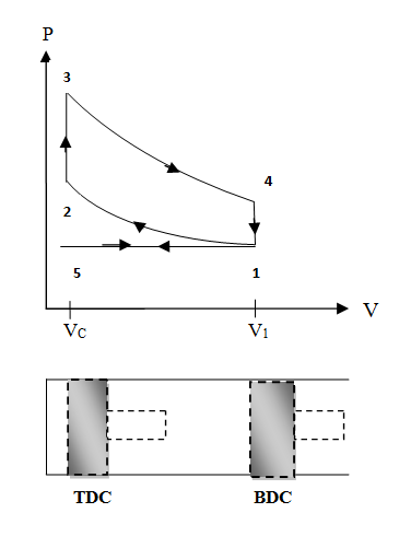
Fig. 12.1 Theoretical working cycle of 4-stroke petrol engine
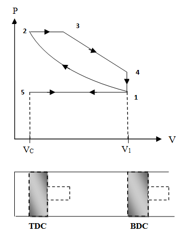
Fig. 12.2 Theoretical working cycle of 4-stroke diesel engine
12.3.1 Combustion process
The heat addition process in an I.C engine is actually a fuel burning or combustion process which is an exothermic reaction between carbon content of fuel and oxygen content of air. The combustion process depends on the type of fuel and other conditions inside the engine and so effecting the way in which heat is released inside the engine and so effecting its thermal efficiency. Thus the overall thermal efficiency of an I.C engine depends on the combustion process itself. In actual the maximum power output, minimum pollution and higher thermal efficiency, all these parameters depend on that how efficiently the combustion process takes place.
12.4 Classification of I.C Engine Based on Ignition Process
Let us now concentrate on I.C engines where the combustion of fuel takes place in the confined volume created by cylinder walls and piston.
Let us understand the combustion process more clearly as:
Combustion may be defined as a relatively rapid chemical combination of hydrogen and carbon in the fuel with the oxygen in atmospheric air and resulting in liberation of heat energy. It is a very complicated phenomenon and has been a subject of intensive research for many years. In fact the whole performance of I.C engine largely depends on the combustion process and pattern of release of heat energy. Hence all scope of research moves around the phenomenon of combustion.
The conditions necessary for combustion to take place are:
i) Presence of a combustible mixture i.e. fuel and air molecules should be in required proportion and in physical contact with each other. Ideally each molecule of fuel should be in close contact with required oxygen molecules.
ii) Some means of initiating combustion i.e. either there should be an external spark or the temperature of fuel air mixture should be very high, well above the ignition temperature of fuel.
iii) Stabilization and propagation of flame in the combustion chamber, which depends on bulk temperature of mixture.
Depending on the method of initiating combustion which further depends on the type of fuel used the I.C engines are further classified as of two types.
i) Spark Ignition (S.I.) Engine or petrol or gas engine.
ii) Compression Ignition (C.I.) Engine-Diesel Engine
12.4.1 Spark ignition (SI) engine
In this type of engine the combustion is initiated by producing a spark by some external means as shown in fig 12.3. The fuel used is petrol, gas or any other liquid fuel which is volatile in nature and the vapour of which can thoroughly mix with air at room temperature to prepare a good combustible mixture. This mixture is prepared outside the engine cylinder in a device called carburetor and sucked by piston in cylinder of engine through inlet valve, thus fulfilling the first requirement of combustion. It is then compressed to a high pressure and temperature, required to fulfill the third condition of combustion. Then last condition is achieved by producing a spark by spark plug. As all the conditions are well achieved, the combustion takes place instantly and sharply increases the pressure and temperature approximately at constant volume at the end of compression stroke. The cycle of SI engines resembles OTTO cycle as shown in fig. 12.1.
12.4.2 Compression Ignition (CI) Engine
In this type of engine the combustion is initiated by compressing the air to such a high pressure & temperature, which is above the ignition temperature of fuel. The fuel used generally is Diesel, which generally does not form mixture with air. Thus the first condition is less achieved due to less volatility of diesel. Hence in this type of engine, first the air only is compressed to a high temperature & pressure and turbulent condition. And then at the end of compression stroke, the fuel is injected and atomized at high pressure in this air as shown in the fig 12.4. Due to atomization the contact area of fuel droplets increases and due to very high temperature produced by compression they vaporizes at once and as the temperature is above the ignition temp the combustion starts at various points. This increases temperature and turbulence further and helps in mixing of fuel and air. The mixing and combustion take place simultaneously and also for a comparatively long time and nearly at constant pressure. Thus the actual engine cycle resembles the Diesel cycle. In Diesel engine, combustion takes longer time by which piston covers some distance and increases the volume of combustible gases in cylinder. The increase in pressure due to release of heat energy is balanced by decrease in pressure due to increase in volume. Thus practically, the pressure remains constant during combustion process in a slow speed Diesel engine. A high speed Diesel engine however works on Dual Combustion Cycle.
12.5 Working of a Four Stroke Otto Cycle Spark Ignition (S.I.) Engine
We have come to know that the working cycle of an actual engine as shown in the fig 12.1 is comprised of all the processes of an Otto cycle along with two addition processes of suction and exhaust. Normally, to carry out a complete cycle of processes as suction, Compression, Ignition, Expansion and Exhaust, piston in the cylinder of engine has to carry out four strokes from one end to other end. Therefore it is also called a four-stroke S.I. engine. The top end position of piston towards the cylinder head is called top dead centre (TDC) and the bottom end position towards crank is called bottom dead centre (BDC).
The theoretical working of a 4-stroke S.I. engine is explained with the help of engine diagram in Fig 12.3 and complete 4-stroke cycle diagram on P-V chart as shown in fig 12.1.
Process 5-1 (Suction stroke)
At the start of cycle the piston moves from TDC to BDC. The inlet valve (I.V.) is opened automatically by valve operating mechanism at the start of this process. Due to increase in volume inside the cylinder, a slight vacuum is created and, the fresh charge i.e. mixture of air and petrol prepared in Carburetor is sucked inside the cylinder through inlet valve. At the end of stroke, the piston reaches BDC position, total volume of cylinder is filled with fresh charge and inlet valve is closed. Theoretically, the charge is filled at constant pressure P1 and it occupies the total volume of cylinder V1.
Process 1-2 (Compression stroke)
During this stroke, both the valves remain closed and piston is moved from BDC to TDC by the force of crank. As the piston moves up, volume of cylinder shrinks and the fresh charge is compressed to a higher pressure P2 and volume V2 equal to clearance volume. Theoretically, this process is adiabatic compression process. Temperature of fresh charge is also raised in compression from T1 to T2.
Process 2-3 (heat addition)
This process is actually a constant volume heat addition process. At point 2, spark plug ignites and starts the combustion of already compressed, high temperature charge. Due to very favorable conditions of combustion, combustion of charge and heat release takes place in no time (theoretically) and pressure & temperature further shoots up to P3 and T3. Theoretically the volume remains constant from ‘2’ to ‘3’. So V2=V3=VC=Clearance Volume.
Process 3-4 (expansion or working stroke)
This is the process or stroke of piston in which positive work is obtained. The burnt gases at high pressure and high temperature at point ‘3’ expand and push the piston again from TDC to BDC, thus doing work on the piston. This work is given to output shaft of engine through connecting rod and crank shaft. A small portion of it is stored in the heavy rotating flywheel mounted on crankshaft, which is used in movement of piston in three other idle stroke i.e. Suction, Compression and Exhaust). When piston reaches BDC, cylindrical total volume is filled with comparatively lower pressure and temperature burnt gases or smoke. At this point 4, the exhaust valve (EV) opens.
Process 4-1 (heat rejection)
In this process, as soon as the exhaust valve is opened at point 4, the burnt gases start escaping to atmosphere and their pressure reduces to atmospheric pressure P1. Theoretically, this process happens in no time and escaping of exhaust gases take away some heat from the engine.
Process 1-5 (exhaust stroke)
This stroke is just opposite to suction
stroke. Piston moves from BDC to TDC and pushes away or sweeps the remaining
burnt gases out through E.V. As the piston reaches TDC most of burnt gases
escape and E.V. is closed. One cycle of the engine completes here.
Simultaneously, the I.V. opens and next cycle starts.
In this way, piston goes on moving or reciprocating from TDC to BDC and BDC to TDC with a high speed and engine produces power continuously by burning of petrol or gas etc. The power output and RPM of engine can be easily controlled by a throttling valve fitted in the passage of air intake or in the carburetor where fuel and air are mixed together in the right proportion. When throttle valve is fully open, maximum air and fuel will be sucked by engine and maximum power will be produced. As throttle valve or accelerator is closed, lesser air and fuel mixture will enter the engine per cycle and lesser power will be produced. The throttle valve can be operated manually or automatically by a governor. In S.I. engine the power output & RPM of engine are governed by varying the quantity of fuel air, mixture. This type of governing is called Quantity Governing.
12.5.1 Actual cycle and valve timing diagram of a 4-s s.i. engine
In the previous article, the theoretical working of a 4-Stroke S.I. Engine based on ‘Otto’ cycle was discussed. But still there are some practical difficulties in operating the engine on theoretical cycle as shown in fig 12.1.Therefore some changes or modifications are required or have to be there to remove practical difficulties. These are being discussed one by one.
1) As the suction of fresh charge and exhaust of burnt gases take place through valves which are practically of far less area than that of piston, some pressure difference is created across these valves. Because of this valve restriction, the processes 5-1 and 1-5 are not on the same line. Suction Process 5-1 line is curved downward due to decrease in pressure in the cylinder caused by valve restriction on one side and pull created by piston on other side. In this way piston has to do extra work in pulling and pushing the gases against valve restriction and also against friction. This work is called pumping work, which is negative and reduces the overall output of engine per cycle. Pumping work is shown by loop 1-5-1 on actual cycle of engine shown in Fig. 12.4.
2) The piston is continuously moving with a high speed and is not stopping at any point. So, volume in the cylinder is continuously changing. On the other hand while operating valves mechanically, they require some finite time to open and close and cannot be operated instantly at a particular state as given in theoretical working. Also practically it is very difficult to suck the fresh charge and throw out the burnt gases exactly within the limit of TDC & BDC. Practically by doing so, these processes become very inefficient. Thus the timing at which valves are operated have to be advanced or delayed from TDC & BDC as discussed in detail below.
3) One more thing is that even the combustion process is very fast in S.I. Engine but it is not completely instantaneous process and has some delay between the ignition of spark and reaching of gases at peak pressure and temperature. Ideally the peak pressure of gases should come just at the point, when piston is about to move from TDC to BDC, so that maximum works is produced.
A typical example of timing of operating Inlet & Exhaust valves and spark plug in a 4-Stroke S.I. Engine is given in terms of Angles of Crank before or after BDC or TDC in Fig. 12.4. If can easily be understood from Fig 12.3. that when piston moves from TDC to BDC, crank rotates by 180° and when it again goes back from BDC to TDC, crank further rotates by 180° and completes 360° or one revolution. But, one working cycle of 4-S Engine completes in four strokes of piston during which crank shaft completes two revolution. Also when piston is at BDC or TDC, crank is exactly aligned with centre line of Cylinder Of Engine.
In the above diagram, dark dot represents the position of crank pin also shown by angle of crank at which valves are operated. The crank pin rotates exactly in circular path. The spiral path is just shown to represent different strokes i.e. Suction, Compression, Expansion and Exhaust separately. From this diagram, only angles are important.
At the start of cycle, inlet valve opens 20° before piston reaching at TDC. Here 20° means crank is making angle 20° with the centre line of cylinder of engine at the moment of opening of inlet valve. It ensures the I.V. is fully open, when piston is at TDC and about to move towards BDC at the start of suction stroke.
The suction stroke ends theoretically when piston reaches BDC. But in actual the closing of I.V. is retarded upto 35° after BDC. It is because during suction, the fresh charge enters the cylinder through I.V. with high momentum due to which it keeps on entering the cylinder even when piston starts moving upward if I.V. is open. So to trap this momentum and to adjust the closing time of I.V., its closing is retarded 35° after BDC to ensure suction of maximum charge in the cylinder.
After I.V. Closing, compression starts at the end of which charge is to be ignited. But to adjust the delay between Ignition and peak pressure, spark is given to charge before the end of compression stroke. It is shown here 35° before TDC. This advancing of spark ensures the peak pressure at TDC position of piston to harness maximum mechanical work during expansion. After Ignition, expansions of burnt gases take place. Theoretically it goes on upto BDC, where E.V. Opens. But practical difficulty is that if E.V. starts opening at BDC, it will fully open after some angle of crank and pressure of gases is still higher, so piston has to do negative work on these gases and net work of cycle will decrease. To avoid this the exhaust valve starts opening 35° before piston reaches BDC during the expansion stroke. It ensures that valve is fully open before BDC and also self escaping of some of burnt gases due to some higher pressure than outside pressure.
At the end of exhaust stroke, E.V. should close theoretically. But to trap the momentum of outgoing gases through E.V. and to ensure minimum exhaust gases left over in the cylinder, exhaust valve closes 10° after TDC.
In this way, by operating the valves and spark before or after BDC/TDC to adjust the real phenomenon, the power output of Engine is optimized. The actual cycle of a 4-S S.I. Engine will look like as shown in fig 12.5.
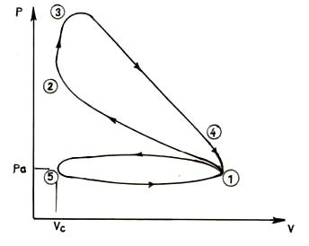
Fig. 12.5 Actual cycle of 4-stroke S.I. engine