Module 6. I. C. engine
Lesson 13
COMPARISON OF SI AND CI ENGINE
13.1 Working of a Four Strock Diesel Cycle Compression Ignition (CI) Engine
A diesel engine is called compression Ignition engine because here the conditions of combustion or ignition are achieved only by compression of air to a very high pressure. There is no spark plug to initiate the combustion, but in place of that a fuel injector is there, which injects and atomizes the fuel i.e. Diesel at a very high pressure in very hot compressed air after compression stroke in engine. Due to high pressure and temperature above the ignition temperature, fuel atomization, evaporation and self ignition take place. The rest of the working of Diesel Engine is same as that of Petrol or Gasoline Engine. Here also one complete cycle is comprised of all the processes of Diesel cycle along with suction of fresh air and exhaust of burnt gases. To carry out all these processes, here also normally 4 strokes of piston are required. So, it is called a 4-stroke Diesel Engine. The complete theoretical working of it is explained here and can be understood with the help of engine line-diagram shown in Fig 13.1. and complete cycle diagram on P-V chart in fig 13.2.
Process 5-1 (suction stroke)
At the start of cycle, the piston moves from TDC (point ‘2’ 2 ‘5)’to BDC (point ‘1’ 2 ‘4) and inlet valve is opened at the start of process at point 5. Due to increase in volume of cylinder by the movement of piston, the fresh air from atmosphere enters the cylinder and occupies all the space inside the cylinder until piston reaches BDC. At the point ‘1’, air filled in cylinder is at volume V1 and its pressure & temperature are theoretically same as that of outside atmosphere. Here inlet valve is closed and cylinder becomes a closed thermodynamic system.
Process 1-2 (compression stroke)
In this stroke, piston moves from BDC to TDC by the force of crank. As both valves are closed, the air sucked in previous stroke is compressed to the clearance volume. Here in Diesel engine the compression ratio ‘r’ which is the ratio of total volume V1 to clearance volume VC is very high as compared to SI Engine. So, naturally the rise in pressure and temperature of air at the end of compression stroke is also more. The range of ‘r’ in Diesel Engine is 15 to 22. Theoretically, the compression process is adiabatic & isentropic Compression.
Process 2-3 (heat addition)
This process is actually a constant pressure heat addition process or a mix of constant volume and constant pressure process as in case of high speed diesel engine. At the point ‘2’ the fuel injector injects a fix quantity of fuel in very hot & compressed air compressed to the clearance volume. Due to that fuel spray ignites itself thus releasing of heat in the cylinder. As this heat addition process is slow, piston moves back to some distance from TDC to point ‘3’ shown in fig 13.2 and the volume increases which nullifies the effect of increase in pressure due to heat addition. Pressure remains constant theoretically upto point 3, where the injector stops injection of fuel and so the addition of heat. Point ‘3’ is also called cut-off point. A part of piston stroke from 2 to 3 takes place along with this process and the burning fuel plus air mixture expand and push the piston producing a positive work.
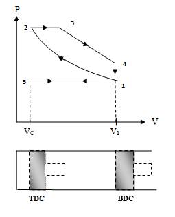
Fig. 13.2 Theoretical working cycle of 4-stroke diesel engine
Process 3-4 (expansion stroke)
Actually the complete expansion stroke is from point 2 to point 4 but a part of it is along the previous heat addition process 2-3. After point ‘3’ heat addition stops and the hot and high pressure burnt gases expand at the cost of their own internal energy and produce positive work by pushing the piston to BDC. This stroke is called working stroke as here piston moves the crankshaft and give mechanical energy. Major part of this energy is given to output shaft and a small portion is stored in heavy flywheel in the form of its rotational kinetic energy and used up during idle strokes of piston i.e. Suction, Compression & Exhaust.
Process 4-1 (heat rejection)
This process takes place at constant volume and heat is rejected directly by escaping of some of burnt gases due to pressure difference inside and outside the engine as soon as exhaust valve opens at point ‘4’ i.e. just at the end of expansion or working stroke. Theoretically, piston remains at BDC and gases escape in no time, taking away some heat from the engine. Pressure inside the cylinder reduces to atmospheric pressure.
Process 1-5 (exhaust stroke)
In this process or stroke, piston is moved by crank from BDC to TDC. As the exhaust valve remains open during this stroke, piston displaces or sweeps out the burnt gases through it and only a small fraction of gases remain in the clearance volume finally. The piston reaches TDC and the cycle completes as the initial conditions are again reached. AT this point, exhaust valve closes and inlet valve opens and next cycle starts.
In this way piston moves or reciprocates from TDC to BDC and again from BDC to TDC with a high speed and engine produces power continuously by burning of air and fuel mixture. The power output and RPM of engine here can be controlled by controlling the quantity of fuel injected only. There is no restriction on the quantity of air sucked by engine. There is a mechanical or electric control on the fuel injection depending on fuel injection system used. When more power is required more quantity of fuel is injected and when less power is required accordingly fuel supply is reduced. There is no control on the quantity of air so air sucked remains more or less same. In this way only the quality of combustible mixture changes in different conditions of loading and so Quality Governing is used in CI Engine.
13.1.1 Actual cycle & valve timing diagram of a 4-s CI engine
In the previous article, the theoretical working of a 4-S Diesel Engine was discussed based on Diesel Cycle. But like in a SI Engine, here also the same type of practical difficulties come in operating the engine, which are to be removed by doing some changes or modifications in valve operating timing and diesel injection timing as per the real phenomenon in a Diesel Engine. All these changes are being discussed here in detail one by one.
1) The inlet and exhaust valves are practically of lesser cross-sectional area than that of piston or cylinder. So they offer flow resistance to the incoming fresh air and outgoing burnt gases. Wall friction & Internal friction is also there. To overcome these resistances, piston has to do negative work for continuously pumping in fresh charge during suction stroke and pumping out the burnt gases during exhaust stroke. So net work is not as given by theoretical cycle shown in fig 13.2. But it is less than that due to negative pumping work which is clear from actual cycle diagram in fig 13.3
2) Inlet and Exhaust valves are to be operated mechanically by a cam shaft which gives a smooth opening & closing. Thus valves cannot be operated instantly at a particular position of piston at BDC or TDC as shown in theoretical cycle in fig 13.2. Also to trap the momentum of incoming air and outgoing burnt gases for the benefit of efficient and effective suction & exhaust stroke, the operation of valves has to be advanced or delayed as discussed in detail further below.
3) The combustion process in a CI Engine is entirely different than that in a SI Engine. Here the fuel injection, its atomization, mixing & burning in air is a relatively slow process, which is to be adjusted appropriately between compression & expansion process so that to maximize the work output.
On removing these practical difficulties and inculcating the necessary changes or modification the actual valve timing diagram of a 4-S CI Engine is shown in Fig 13.4.
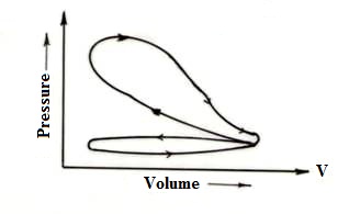
Fig. 13.3 Actual cycle of 4-S CI engine
At the start of cycle, inlet valve opens at crank position 25° before TDC to adjust the valve operating period. It ensures the valve is fully open at the start of suction stroke just after TDC.
At the end of suction stroke at BDC, Inlet valve should close as per theoretical cycle. But as discussed earlier also, it closes 30° after BDC i.e. after the piston has started moving upwards to adjust the valve operating period and to trap the incoming momentum of fresh air at the end of suction stroke.
As soon as the inlet valve closes, compression of air starts and at the end of it injection of fuel should start theoretically. But to adjust the time delay between start of injection and start of combustion, fuel injector starts injecting the fuel 15° before TDC. It keeps on injecting fuel upto 25° after TDC. Rise in pressure due to combustion is somewhat adjusted by increase in volume by downward movement of piston. Thus there is no steep rise in pressure as was in case of SI Engine. It is clear from actual PV diagram shown in fig 13.3
Like in SI Engine, exhaust valve starts opening 45° before piston reaching BDC so as to adjust the valve operating timing and to decrease pumping work of piston during exhaust stroke. However, opening of E.V. before end of expansion stroke is also a direct loss of power but that will be lesser & safer than the piston would have to face a opposing thrust or jerk just at the start of exhaust process.
At the end of exhaust stroke, when piston is at TDC, exhaust valve should close as per theoretical cycle in fig. 13.2. But to trap the momentum of outgoing gases and also to adjust the valve operating period, E.V. closes fully 15° after TDC.
In this way by operating the valves and fuel injector before and after BDC/TDC to adjust the real phenomenon the power output of engine is optimized. After incorporating all these changes or modifications, the actual cycle of a 4-S Diesel Engine will look like as shown in fig. 13.3
Table 13.1 Comparison of SI and CI engines
|
SI Engine |
CI Engine |
|
Fuel used is petrol, LPG or CNG etc. |
Fuel used is Diesel oil. |
|
It works on ‘OTTO’ cycle. |
It works on Diesel or Dual combustion cycle. |
|
Power Required to start the engine is less |
Power required to start the engine is more. |
|
Compression ratio is low in the range of 7 to 9. |
Compression ratio is high in the range of 15 to 24. |
|
Fuel supply system is either through carburetor or through Electronic Multi Point Fuel Injection (MPFI) system. |
Fuel supply system is any type of high pressure fuel injection system like Direct Injection (D.I.), Common Rail Diesel Injection (CRDI) etc. |
|
Maximum pressure does not exceed 60 bars. So SI engine is comparatively light in weight. |
Maximum pressure exceeds up to 120 bar or even more. So, more robust construction and heavier than SI Engine. |
|
High RPM, Low Torque |
Low RPM, High Torque |
|
Power output is governed by controlling the quantity of fresh charge supply to engine. So SI Engine uses quantity governing. |
Power output is governed by controlling the quantity of fuel only to be injected while air quantity remains same. So CI engine uses quality governing. |
|
Its running cost is high. (Less fuel efficiency) |
Its running cost is low. (More fuel efficiency) |
|
Its initial cost is low. |
Its initial cost is high. |
|
It’s maintenance cost is low. |
Its maintenance cost is high. |
|
Not used in case of high power requirement due to lesser fuel efficiency |
Not used in case of low power requirement due to bulky and costly. |
|
It has high power to weight ratio. |
It has low power to weight ratio |
|
Their use is limited to two wheeler automobiles and personal cars only. May also be used in some other small applications where light engine is primary requirement. |
These are used in heavy duty vehicles, Electric Gen Sets and other heavy duty power applications where low running cost is primary requirement. |