Module 7. Performance of I. C. engine
Lesson 17
PERFORMANCE PARAMETERS OF IC ENGINE
17.1 Performance Parameters
The job of an internal combustion engine is to convert heat energy into mechanical energy. Practically it means that an IC engine of any type produce mechanical work in the form of a rotating shaft giving some torque at some value of r.p.m by continuously burning of fuel. Performances of IC engine means that how will it complete the above mentioned job. It can be measured or compared only in terms of certain parameters as mentioned in this chapter. These parameters are called performance parameters.
17.1.1 Indicated Power (IP)
The total power
developed by combustion of fuel in the combustion chamber is called Indicated
Power (IP). It can be calculated as:
![]() .........
(Eq. 17.1)
.........
(Eq. 17.1)
Where n = number of cylinders
Pmi = Indicated mean effective pressure, (bars)
L = Length of stroke, (m)
A = Area of piston, (m2)
K = ½ for 4 stroke engine
= 1 for 2 stroke engine
Indicated power is the total power of engine which is graphically represented by area of cycle on P-V chart. As the actual P-V diagram of an engine is drawn by an indicator mechanism, this power is called indicated power.
17.1.2 Brake Power (BP)
The power
available at an engine’s output shaft is called its brake power. It is the
power which can be positively used against resistive force or braking force of
the application for which engine is being used. It can be calculated as
![]() ………
(Eq. 17.2)
………
(Eq. 17.2)
Where
N = engine speed in rpm
T = Torque at output shaft in N-m.
![]() .........
(Eq. 17.3)
.........
(Eq. 17.3)
Where Pmb = Brake mean effective pressure.
All other notations are same as in the expression of I.P. given in equation 17.1.
Comparing equations 17.2 and 17.3, Torque T= Constant × AL× Pmb
Thus the torque of an engine depends on its size (AL) and mean effective pressure. Torque of a given engine of constant size will be more when its mean effective pressure is more. Hence, mean effective pressure is a true parameter to compare power of engines.
17.1.3 Frictional power
It is the power required to overcome the internal friction of engine. It represents the total losses occurred from indicated power. It is the difference between Indicated power and Brake Power.
F.P = I.P – B.P ……… (Eq. 17.4)
17.1.4 Mechanical efficiency
It is the ratio of brake power to the indicated power of an IC Engine.
![]() ………
(Eq. 17.5)
………
(Eq. 17.5)
17.1.5 Mean effective pressure
(a) Indicated Mean Effective Pressure (i.m.e.p.)
It is defined as the hypothetical pressure which is thought to be acting on the piston throughout the power stroke and does the work equal to mechanical work generated per cycle of engine. It is also called indicated mean effective pressure as it is usually determined with the help of a P-V diagram taken with the help of an indicator mechanism. The area of PV diagram drawn by indicator mechanism can be calculated by any measurement method. Then, the indicated mean effective Pressure can be determined as:
![]()
It is also clear from fig 17.1.
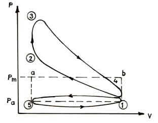
Fig. 17.1 Indicated mean effective pressure
(b) Brake mean efficiency pressure (b.m.e.p.)
It is also a hypothetical mean effective pressure acting on the piston and which is based on braked power just like i.m.e.p (Indicated mean Effective Pressure) is based on indicated power. If there is no friction or other losses than b.m.e.p will be equal to i.m.e.p.
As power depend on size and speed therefore it is not possible to compare engines on the basis of either power or torque. However, the mean effective pressure is the true indication of relative performance of different engines.
17.1.6 Specific output
It is
defined as the brake power output per unit of piston displacement. It is a
parameter which relates the power of an engine with its size so it is an
important performance parameter.
![]() ………
(Eq. 17.6)
………
(Eq. 17.6)
So, for same piston displacement and brake mean effective pressure, engine running at higher speed will give more power.
Therefore, power of an engine is always specified with its r.p.m.
17.1.7 Volumetric efficiency
It is defined as
the ratio of actual volume (as reduced to NTP) of the charge or air drawn in
during the suction stroke to the swept volume of piston. (NTP: Normal temperature and pressure)
![]() ………(Eq. 17.7)
………(Eq. 17.7)
We know that due to flow resistance offered by valves, intake manifold etc, the pressure of fresh charge filled in the cylinder will be less than outside atmospheric pressure. Also due to continuous ignition, temperature inside the engine is higher than outside. Thus for charge drawn volume is same but its pressure is less and its temperature is high.
When this charge is reduced to normal pressure and temperature outside, its actual volume will be less than swept volume of engine.
Volumetric efficiency is an important performance parameter, which directly affects the power output of engine. More is the volumetric efficiency more is the charge sucked per stroke and more power is produced.
17.1.8 Fuel air ratio
It is the ratio of mass of fuel to the mass of air in the fuel air mixture. Sometimes it may be given as Air-fuel ratio i.e. mass of air to mass of fuel.
17.1.9 Relative fuel air ratio
It is defined as the ratio of actual fuel air ratio to that of stoichiometric fuel air ratio or chemically correct fuel air ratio. Stoichiometric fuel air ratio is that ratio in which complete combustion of fuel takes place and no excess air is left. It has a fix value for a given fuel depending on its chemical formula and reaction. In a given fuel air mixture, if relative fuel air ratio is less than 1 it is a lean mixture and if it is more than 1, it is a rich mixture.
17.1.10 Specific fuel consumption
It is the mass of fuel consumed in kg/hour per kW of power developed by engine.
![]()
It is a clear indicator of efficiency with which the engine burns fuel to produce power and is very important performance parameter.
17.1.11 Thermal efficiency
It is the ratio of work done or power developed by an engine to the rate of chemical energy or heat supplied by burning of fuel in the engine. It can be based on indicated power or brake power and accordingly can be specified as
![]()
![]()
Where,
mf = Rate of fuel consumed (kg / sec)
C = calorific value of fuel (kJ/ kg)
I.P. = Indicated power (kW)
B.P. = Brake power (kW)
17.1.12 Heat balance sheet
The real picture of overall performance of an engine can be made clear by its heat balance sheet. Heat balance sheet of an engine is prepared by running it under steady state conditions i.e. at constant load and r.p.m. The work produced is measured with the help of P-V diagram drawn by indicator mechanism. Other parameters noted are: quantity of fuel used in a given time, Calorific value of fuel, cooling water flow rate and its inlet and outlet temperatures, weight of exhaust gases and their temperature. Calculations can be done based on this data to find account of all heat input. A sample of heat balance sheet is given:
(a) Total heat input
It can be calculated as the product of rate of mass of fuel used and its calorific value.
(b) Total output
i) Heat absorbed in producing Indicated Power or the heat energy converted to work. It can be calculated by indicator mechanism
ii) Heat taken away by Cooling Water:
It can be calculated as Mw × Cw × (t0 – ti)
Where,
Mw=Cooling Water flow rate
Cw = Specific heat of cooling water
ti = Inlet temperature of Cooling Water
t0 = Outlet temperature of Cooling Water
iii) Heat taken away by exhaust gases:-
It can also be calculated likewise as Me × Cpg × (te – tr)
Where,
Me = Mass of exhaust gases produced in a given time
Cpg = Specific heat of exhaust gases
te = temperature of exhaust gases
tr = room temperature
iv) Heat unaccounted for:-
It is the heat energy which is not accounted and is difference of total heat input minus sum of above three components of output. It is due to loss of heat by radiation and other unaccounted losses.
17.1.13 Specific weight
It is defined as the weight of engine in kg per BHP developed. It is an indicator of engine bulk.
17.2 Measurement of Brake Power
Brake power is measured by measuring the external braking force or resistive force which is given to engine and r.p.m of engine at which it is able to run on bearing or taking that resistive force. The braking force can be offered to engine output shaft by any of the mechanical or electrical method in a dynamometer. Dynamometer is a device used for measurement of power output of an engine by measuring the resistive force and r.p.m of engine. A rope dynamometer is a simple device which can easily be used for measuring brake power of an engine in a laboratory and is explained as follows:
17.2.1 Rope dynamometer
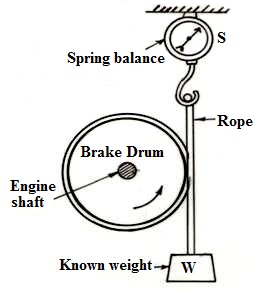
Fig. 17.2 Rope dynamometer
It is a simple device in which a brake drum is fitted over the engine output shaft and over the circumference of which, a rope is wrapped. One end of rope is fixed to a spring balance hinged above the drum in a vertical line touching the circumference of drum. Other end of drum is carrying some calculated weight a shown in fig 17.2. When the engine is not running the reading in spring balance is same as the weight tied to the bottom end of rope. But when engine rotates the drum in a direction of lifting of weight, the reading in spring balance will reduce because of the braking force between rope and drum. This braking force is due to rotation of drum at a given r.p.m and balanced by the output force of engine. This force is given by the difference of fix weight, W and new reading in spring balance (S).
The calculation for the measurement of brake power is as follows:
In a Rope Dynamometer let us assume that
W = Weight at end of rope in Newton
S = spring balance reading in Newton
N = Engine r. p. m
D = Diameter of brake in ‘m’
d = diameter of rope in ‘m’
D + d = effective diameter
Then Work done or power developed
by engine
![]()
![]()
17.3 Measurement of Indicated Power
Indicated power can be measured in two ways as directly and indirectly.
17.3.1 Direct method
Indicated Power can be directly calculated by finding the indicated mean effective pressure Pmi from indicator diagram and putting in the expression of I.P. given in eqn17.1
17.3.2 Indirect method
This method is applicable to a multi-cylinder engine only. For example let us take the case of a 4-cylinder engine. Then its total indicated power, ‘I’ will be the sum of indicated power of individual cylinders i.e.
I = I1+I2+I3+I4.
Let total brake power is B.
If we disconnect the cylinder one from generating power by cutting its fuel supply and maintain the same r.p.m by reducing load then let the power generated is B1. In the same way let the brake power after disconnecting… cylinder 2, 3, 4 is B2, B3, & B4.
If L1, L2, L3, L4 is the power loss in each of the four cylinders, then
B = (I1-L1) + (I2-L2) + (I3-L3) + (I4-L4)
And B1 = (0 - L1) + (I2 - L2) + (I3 - L3) + (I4 - L4)
So,
I1 = B - B1
I2 = B – B2
I3 = B – B3
I4 = B – B4
Then the total indicated power of engine will be equal to I=I1+I2+I3+I4
And Frictional Power, F.P = I – B