Module 8 . Measuring instruments
Lesson 24
VENTURIMETER AND PITOT TUBE
24.1 Introduction
Measuring the flow of liquids is a critical need in many industrial plants particularly dairy and food processing plants. Flow measurement is the quantification of bulk fluid movement. Flow can be measured in a variety of ways. Positive-displacement flow meters accumulate a fixed volume of fluid and then count the number of times the volume is filled to measure flow. Other flow measurement methods rely on forces produced by the flowing stream as it overcomes a known constriction, to indirectly calculate flow. Flow may be measured by measuring the velocity of fluid over a known area. A flowmeter is an instrument used to measure linear, nonlinear, mass or volumetric flow rate of a liquid or a gas. Both gas and liquid flow can be measured in volumetric or mass flow rates, such as liters per second or kilograms per second. These measurements can be converted between one another if the material's density is known.
24.2 Venturimeter
Venturimeter is used to the measurement of flow rate. It is generally used for large diameter pipes.
24.2.1 Construction

Fig. 24.1 Venturimeter
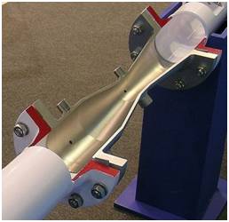
Fig. 24.2 Venturimeter (cut view)
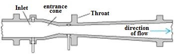
Fig. 24.3 Venturimeter section
The venturi tube has a entrance zone, converging conical inlet, a cylindrical throat, and a diverging recovery cone. The main sections of venturimeter are indicated in Fig. 24.3.
a) Entrance Section
It is a straight cylinder having length equal to 5 to 8 times the diameter of the pipe.
b) Convergence Section:
Here, the diameter of the tube gradually decreases. The angle of cone is a1 = 21 ± 5°. When liquid flows inside the venturimeter, the velocity of fluid increases and correspondingly the pressure falls.
c) Throat: At this section, the diameter of the venturemeter is minimum. Velocity is maximum and pressure is minimum. Throat diameter = 1/3 to 1/4th inlet diameter.
d) Diverging section: Again the diameter of the tube gradually increases. Here due to gradual divergence pressure is build up to the original inlet pressure. The cone angle is 5-7°.
Small size venturimeter are made of brass or, bronze and large venturimeters are made of cast iron or stainless steel.
24.2.2 Working principle
In the venturimeter the fluid is accelerated through a converging cone of angle 21 ± 2° and the pressure difference between the upstream side of the cone and the throat is measured and provides a signal for the rate of flow.
The fluid slows down in diverging cone with smaller angle (5 - 7°) where most of the kinetic energy is converted back to pressure energy. High pressure and energy recovery makes the venturimeter suitable where only small pressure heads are available.
Flow rate can be given as:
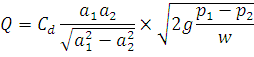
Where,
Q = flow rate,
Cd = Coefficient of discharge. It is not constant and depends on pipe geometry, Reynolds number of the flow etc.
a1 = area at the entrance of venturi
a2 = area at the venturi throat
p1 = Pressure at entrance of venture
p2 = Pressure at venture throat
w = ρg
24.2.3 Advantages
1. The venturi tube is suitable for clean, dirty and viscous liquid and some slurry services.
2. Loss of head due to installation in the pipeline is small.
3. Original pressure of the liquid can be recovered completely.
4. Accuracy is 1% of full range
5. Not much wear and tear.
6. Characteristics are well established and it is in use since years.
7. Can be used for large flow rates and large diameter pipes.
24.2.4 Disadvantages
1. Space requirements are more.
2. Expensive in installation.
3. Has to be designed as per requirement.
24.3 Pitot Tube
Pitot tube is used to measure flow velocity. The construction of Pitot tube is shown in Fig. 24.4. Outer body of pilot tube consist of ports at point A, for sensing the static pressure of fluid. At point B fluid vel. become zero and inner tube is for sensing the stagnation pressure. The outlet C & D is connected to U-tube manometer for measuring the pressure difference between the points A and B.
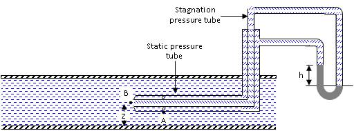
Fig. 24.4 Pitot tube
The flow velocity is given by the following equation:
Flow
velocity ![]()