Module 8. Measuring instruments
Lesson 25
ROTAMETER, WATER LEVEL POINT GAUGE, HOOK GAUGE
25.1 Rotameter
A Rotameter is a device that measures the flow rate of liquid or gas in a closed tube. It belongs to a class of meters called variable area meters, which measure flow rate by allowing the cross-sectional area the fluid travels through to vary, causing some measurable effect.
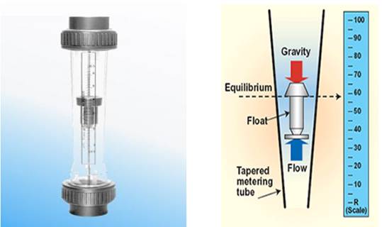
Fig. 25.1 Rotameter
25.1.1 Construction
It consist of tapered, metered metering glass tube inside of which is located a rotor or active element (float). The tube is provided a suitable inlet and outlet connection. The float has a specific gravity higher than that of fluid. As the fluid flows through the tube, the float rises. Equilibrium will be reached when pressure and the buoyancy of the float counterbalance gravity. The float's height in the tube is then used to reference a flow rate on a calibrated measurement reference.
25.1.2 Principle of working
The rotameter's operation is based on the variable area principle: fluid flow raises a float in a tapered tube, increasing the area for passage of the fluid. The greater the flow, the higher the float is raised. The height of the float is directly proportional to the flowrate. With liquid, the float is raised by a combination of the buoyancy of the liquid and the velocity head of the fluid. With gases, buoyancy is negligible, and the float responds to the velocity head alone.
The float moves up or down in the tube in proportion to the fluid flowrate and the annular area between the float and the tube wall. The float reaches a stable position in the tube when the upward force exerted by the flowing fluid equals the downward gravitational force exerted by the weight of the float. A change in flowrate upsets this balance of forces. The float then moves up or down, changing the annular area until it again reaches a position where the forces are in equilibrium. To satisfy the force equation, the rotameter float assumes a distinct position for every constant flowrate. However, it is important to note that because the float position is gravity dependent, rotameters must be vertically oriented and mounted.
Discharge (Q) is given as:
Where,
Q = Discharge
Cd = Discharge coefficient
ρf = Density of fluid
ρ = Density of float
Af= Maximum cross sectional area of float.
aft = annular area between float & tube.
25.1.3 Advantages
1. Simpler in operation.
2. No external power or energy required for its operation.
3. Ease of handling & installation.
4. Relatively low cost.
5. Can handle corrosive fluids.
25.1.4 Types of rotameters
On basis of construction rotameters can be classified as follows:
a. Glass tube Rotameters
b. Metal Tube Flowmeters
c. Plastic Tube Rotameters
a. Glass tube rotameters
The basic rotameter is the glass tube indicating-type. The tube is precision formed of borosilicate glass, and the float is precisely machined from metal, glass or plastic. The metal float is usually made of stainless steel to provide corrosion resistance. The float has a sharp metering edge where the reading is observed by means of a scale mounted alongside the tube.
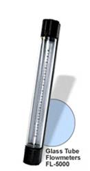
(Source: http://www.omega.com/prodinfo/rotameters.html)
Fig. 25.2 Glass tube rotameter
End fittings and connections of various materials and styles are available. The important elements are the tube and float, often called the tube-and-float combination, because it is this portion of the rotameter which provides the measurement. In fact, similar glass tube and stainless steel float combinations are generally available. The scale of the rotameter can be calibrated for direct reading of water, or it may have a scale to read a percent of range or an arbitrary scale to be used with conversion equations or charts. Safety-shielded glass tube rotameters are in general use throughout industry for measuring both liquids and gases. They are manufactured with end fittings of metal or plastic to meet the chemical characteristics of the fluid being metered. The only fluids for which these meters are not suited are those which attack glass metering tubes, such as water over 90°C (194°F), with its high pH which softens glass; wet steam, which has the same effect; caustic soda, which dissolves glass; and hydrofluoric acid, which etches glass.
b. Metal tube rotameter
(Source: http://www.omega.com/prodinfo/rotameters.html)
Fig. 25.3 Metal tube rotameter
For higher pressures and temperatures beyond the practical range of glass tubes, metal tubes are used. These are usually manufactured in aluminium, brass or stainless steel. The position of the piston is determined by magnetic or mechanical followers that can be read from the outside of the metal metering tube. Similar to glass tube rotameters, the spring-and-piston combination determines the flowrate, and the fittings and materials of construction must be chosen so as to satisfy the demands of the applications. These meters are used for services where high operating pressure or temperature, water hammer, or other forces would damage glass metering tubes. Spring and piston flowmeters can be used for most fluids, including corrosive liquids and gases. They are particularly well suited for steam applications, where glass tubes are unacceptable.
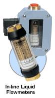
c. Plastic tube rotameters
(Source: http://www.omega.com/prodinfo/rotameters.html)
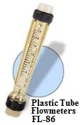
Fig. 25.4 Plastic tube rotameter
Plastic tubes are also used in some rotameter designs due to their lower cost and high impact strength. They are typically constructed of polycarbonate, with either metal or plastic end fittings. With plastic end fittings, care must be taken in installation, not to distort the threads. Rotameters with all plastic construction are available for applications where metal wetted parts cannot be tolerated, such as with deionized water or corrosives.
25.2 Water Level Gauge
a. Gauge glass
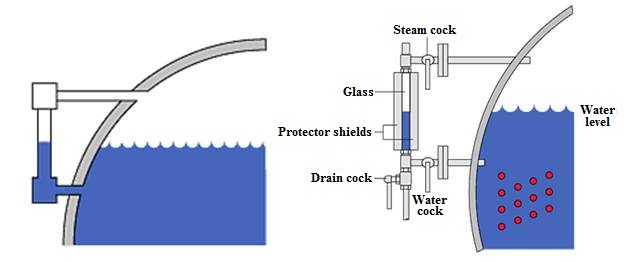
Fig 25.5 Gauge glass indicating liquid level in horizontal tank
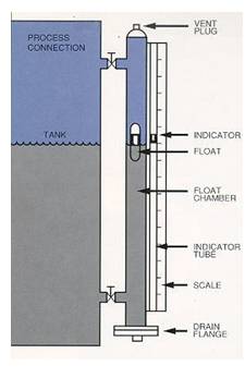
Fig 25.6 Gauge glass indicating liquid level in vertical tank
b. Float type gauge
i. Ball Float
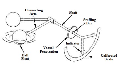
Fig 25.7 Ball float
The ball float method is a direct reading liquid level mechanism. The most practical design for the float is a hollow metal ball or sphere. However, there are no restrictions to the size, shape, or material used. The design consists of a ball float attached to a rod, which in turn is connected to a rotating shaft which indicates level on a calibrated scale (Fig. 25.7). The operation of the ball float is simple. The ball floats on top of the liquid in the tank. If the liquid level changes, the float will follow and change the position of the pointer attached to the rotating shaft.
ii. Chain Float
This type of float gauge has a float ranging in size up to 12 inches in diameter and is used where small level limitations imposed by ball floats must be exceeded. The range of level measured will be limited only by the size of the vessel. The operation of the chain float is similiar to the ball float except in the method of positioning the pointer and in its connection to the position indication. The float is connected to a rotating element by a chain with a weight attached to the other end to provide a means of keeping the chain taut during changes in level (Fig. 25.8).
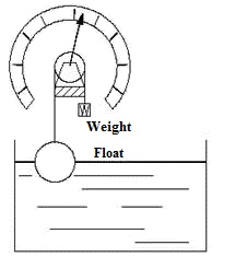
Fig. 25.8 Chain float
25.3 Hook Gauge
Pointer gauge has a circular rod having one end attached to scale and the other being a pointed one. The pointed end touches the water and the other is attached to scale. The device consists of a sharp hook suspended from a micrometer cylinder, with the body of the device having arms which rest on the rim of a still well. The change in water level is determined by the difference in readings.
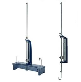
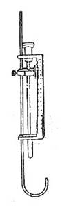
Fig 25.9 Hook gauge
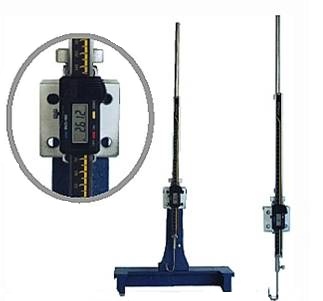
Fig 25.10 Hook gauge with digital display