Module 1. Instruments and measurement system
Lesson 2
Elements of generalized measurement system
2.1 Introduction
Scientists, engineers and other humans use a vast range of instruments to perform their measurements. These instruments may range from simple objects such as ruler scales and stopwatches to electron microscopes and particle accelerators used by scientists and engineers.
An instrument is as a device or a system which is designed to maintain a functional relationship between prescribed properties of physical variables being measured. It provides the means of communication to a human observer or the operator of a machine or equipment. The above stated functional relationship remains valid, only as long as the static calibration of system remains constant. The performance of an instrument of a measurement system is usually described in terms of a set of its static and dynamic characteristics. These characteristics have been described in detail in lessons 6 and 7.
2.2 Functional Elements of a Measurement System
To understand a measuring instrument/system, it is important to have a systematic organization and analysis of measurement systems. The operation of a measuring instrument or a system could be described in a generalized manner in terms of functional elements. Each functional element is made up of a component or groups of components which perform required and definite steps in the measurement. The functional elements do not provide the intricate details of the physical aspects of a specific instrument or a system. These may be taken as basic elements, whose scope is determined by their functioning rather than their construction.
The main functional elements of a measurement system are:
i) Primary sensing element
ii) Variable conversion element
iii) Variable manipulation element
iv) Signal conditioning element
v) Data transmission element
vi) Data presentation element.
2.2.1 Primary sensing element
The quantity or the variable which is being measured makes its first contact with the primary sensing element of a measurement system. The measurement is thus first detected by primary sensor or detector. The measurement is then immediately converted into an analogous electrical signal. This is done by a transducer. Though a transducer in general, is defined as a device which converts energy from one form to another. But in measurement systems, this definition is limited in scope. A transducer is defined as a device which converts a physical quantity into an electrical quantity. The output of the sensor and detector element employed for measuring a quantity could be in different analogous form. This output is then converted into an electrical signal by a transducer. This is true of most of the cases but is not true for all. In many cases, the physical quantity is directly converted into an electrical quantity by a detector transducer. The first stage of a measurement system is known as a detector transducer stage.
2.2.2 Variable conversion element
The output signal of the variable sensing element may be any kind. It could be a mechanical or electrical signal. It may be a deflection of elastic member or some electrical parameter, such as, voltage, frequency etc. Sometimes, the output from the sensor is not suited to the measurement system. For the instrument to perform the desired function, it may be necessary to convert this output signal from the sensor to some other suitable form while preserving the information content of the original signal. For example, suppose the output from the sensing element is in the form of very small displacement which is difficult to measure mechanically, it is converted in to corresponding electrical signal with the help of transducer called stain gauge for further processing. Also if the output at one stage is analogue form and the next stage of the system accepts input signal only in digital form. In such cases, we will have to use as Analogue /Digital converter.
In many instruments variable conversion element is not required. Some instruments/measuring systems may require more than one element.
2.2.3 Variable manipulation element
Variable manipulation means a change in numerical value of the signal. The function of a variable manipulation element is to manipulate the signal presented to this element while preserving the original nature of the signal. For example, a voltage amplifier acts as a variable manipulation element. The amplifier accepts a small voltage signal as input and produces an output signal which is also voltage but of greater magnitude. The variable manipulation element could be either placed after the variable conversion element or it may precede the variable conversion element.
2.2.4 Signal conditioning element
The output signal of transducers contains information which is further processed by the system. Many transducers develop usually a voltage or some other kind of electrical signal and quite often the signal developed is of very low voltages, may be of the order of mV and some even µV. This signal could be contaminated by unwanted signals like noise due to an extraneous source which may interfere with the original output signal. Another problem is that the signal could also be distorted by processing equipment itself. If the signal after being sensed contains unwanted contamination or distortion, there is a need to remove the interfering noise / sources before its transmission to next stage. Otherwise we may get highly distorted results which are far from its true value.
The solution to these problems is to prevent or remove the signal contamination or distortion. The operations performed on the signal, to remove the signal contamination or distortion, is called Signal Conditioning. The term signal conditioning includes many other functions in addition to variable conversion and variable manipulation. Many signal conditioning processes may be linear, such as, amplification, attenuation, integration, differentiation, addition and subtraction. Some may be non-linear processes, such as, modulation, filtering, clipping, etc. The signal conditioning processes are performed on the signal to bring it to the desired form for further transmission to next stage in the system. The element that performs this function in any instrument or instrumentation system is known as Signal Conditioning Element.
2.2.5 Data transmission element
There are several situations where the elements of an instrument are actually physically separated. In such situations it becomes necessary to transmit data from one element to another. The element that performs this function is called a Data Transmission Element. For example satellites or the air planes are physically separated from the control stations at earth. For guiding the movements of satellites or the air planes control stations send the radio by a complicated telemetry systems. The signal conditioning and transmission stage is commonly known as Intermediate Stage.
2.2.6 Data presentation element
The function of data presentation element is to convey the information about the quantity under measurement to the personnel handling the instrument or the system for monitoring, control, or analysis purposes. The information conveyed must be in a convenient form. In case data is to be monitored, visual display devices are needed. These devices may be analogue or digital indicating instruments like ammeters, voltmeters, etc. In case the data is to be recorded, recorders like magnetic tapes, high speed camera and T.V. equipment; storage type C.R.T., printers, analogue and digital computers may be used. For control and analysis purpose computers and the control elements are used. The final stage in a measurement system is known as terminating stage.
Figure 2.1 below presents the block diagram of functional elements of a generalized measuring system / instrument. One must understand the difference between functional elements and the physical elements of measuring system. Functional element indicates only the function to be performed. Physical elements are the actual components or parts of the system. One physical element can perform more than one function. Similarly one function could be performed by more than one physical element. This is more suitably illustrated in the example of a measuring instrument described below.
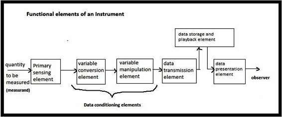
Fig. 2.1 Block diagram of functional elements of a measurement system / instrument
2.3 Functional Elements of a Bourdon Pressure Gauge
As an example of a measurement system, consider the
simple Bourdon tube pressure gauge as shown in Fig. 2.2. This gauge offers a
good example of a measurement system. In this case, the Bourdon tube acts as
the primary sensing element and a variable conversion element. It senses the input
quantity (pressure in this case). On account of the pressure the closed end of
the Bourdon tube is displaced. Thus, the pressure is converted into a small
displacement. The closed end of the Bourdon tube is connected through
mechanical linkage to a sector-pinion gearing arrangement. The gearing
arrangement amplifies the small displacement and makes the pointer to rotate
through a large angle. The mechanical linkage thus acts as a data transmission
element while the gearing arrangement acts as a data manipulation element. The
dial scale on the gauge body plays the function of data presentation element
and conveys the information about the quantity being measured. The information
conveyed by this device is in analogue form.
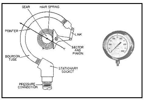
Fig. 2.2 Bourdon Pressure gauge, the pressure measuring instrument
2.4 Functional Elements of a Clinical Thermometer
As another example of a measurement system, let us consider the simple clinical thermometer shown in Fig. 2.3. In this case, the thermometer bulb containing mercury acts as the primary sensing element as well as a variable conversion element. It senses the input quantity, the temperature. On account of the increase in temperature the mercury in bulb expands and its volume is increased. The temperature signal is converted into volume displacement. As the mercury expands it move through the capillary tube in the thermometer stem, integrated to the bulb. The cross section area of the capillary being constant, the volume signal is thus converted into linear distance signal. The capillary thus has the role of signal manipulation and data transportation elements. The final data presentation stage consists of the scale on the thermometer stem, which is calibrated to give the indication of the temperature signal applied to the thermometer bulb. A restriction bend is provided in the clinical thermometers at the junction of the bulb and the capillary, which does not allow the back flow of mercury to the bulb once it has expanded to the capillary. Thus the restriction in the capillary acts as the data storage function of the instrument.
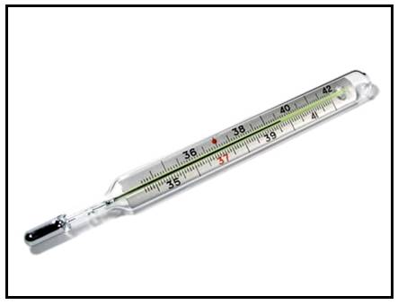
Fig. 2.3 Clinical thermometer, the temperature measuring instrument
If the measurement is done to control a parameter / process then a control device is integrated at the final measurement stage. In such cases, it is necessary to apply some feedback to the input signal to accomplish the control objectives. The control stage compares the signal representing the measured variable provided by the measurement system with a reference signal of the same form. This reference signal has a value to which the measured signal should be controlled. If the measured signal agrees with the reference value, the controller does nothing. However, if there is a difference between the measured value and the reference value, an error signal is generated. Thus, the controller sends a signal to a device which acts to alter the value of the measured signal.
Suppose the measured variable is flow of a liquid, then the control device is a motorized valve placed in the flow system. The measurement system measures the flow rate. In case the measured flow rate is too low than the desired preset flow rate, then the controller would make the valve to open more, thereby increasing the flow rate. If on the other hand, the flow rate is too high, the valve is closed to the require position. The operation of closing or opening of valve will cease when the output flow rate is equal to preset value of flow rate.