Module 2. Classification and selection of instruments
Lesson 4
Analog and Digital Modes of Operation
4.1 Introduction
Working with absolute instruments for routine work is time consuming since every time a measurement is made, it takes a lot of time to compute the magnitude of the quantity under measurement. It is the secondary instruments which are most generally used in everyday work, the use of the absolute instruments being merely confined within laboratories as standardizing instruments. Secondary instruments work in two modes, the Analog mode and the Digital mode.
4.2 Analog or Analogue Signal
Analog signals are those which vary in a continuous fashion and take on infinity of values in any given range. The devices which produce these signals are called analog devices. Analog is usually thought of in an electrical context; however, mechanical, pneumatic, hydraulic, and other systems may also convey analog signals. An analog signal uses some property of the medium to convey the signal's information. For example, an aneroid barometer uses rotary position as the signal to convey pressure information. Electrically, the property most commonly used is voltage followed closely by frequency, current, and charge. The devices that produce such signals are called analog devices.
Any information may be conveyed by an analog signal. Often such a signal is a measured response to changes in physical phenomena, such as temperature, pressure, sound or position and is achieved using a transducer. An analog signal is one where at each point in time the value of the signal is significant. For example, in sound recording, fluctuations in air pressure (that is to say, sound) strike the diaphragm of a microphone which induces corresponding fluctuations in the current produced by a coil in an electromagnetic microphone, or the voltage produced by a condenser microphone.
4.3 Digital Signal
In contrast the analog signals which vary in a continuous fashion and take on infinity of values in any given range, the digital signals vary in discrete steps and thus take up only finite different values in a given range. The devices that produce such signals are called digital devices.
Analog and Digital signals are presented in Fig. 4.1 (a) and (b). In an analog system, the function varies continuously. On the other hand, the digital values are discrete and vary in equal steps. The figure below illustrates how both an analog voltage and a digital voltage vary with time.
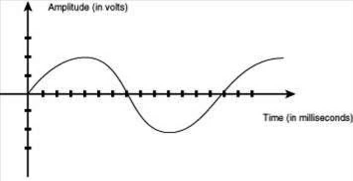
Fig. 4.1(a) Analog signal
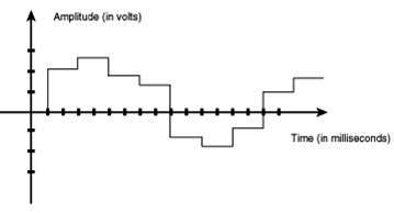
Fig. 4.1(b) Digital signal
4.4 Analog Versus Digital Modes
An analog signal is one where at each point in time the value of the signal is significant, where as a digital signal is one where at each point in time, the value of the signal must be above or below some discrete threshold. The display of the quantity to be measured in analog instruments is in terms of deflection of a pointer, where as digital instruments indicate the value to be measured in terms of decimal number. The main advantage of the analog signal is its fine definition which has the potential for an infinite amount of signal resolution. Compared to digital signals, analog signals are of higher density.
Another advantage with analog signals is that their processing may be achieved more simply than with the digital equivalent. An analog signal may be processed directly by analog components, though some processes aren't available except in digital form. The analog instruments are less costly and simple in design as compared to their digital counter parts.
The primary disadvantage of analog signaling is that any system may have noise, that is, random unwanted variation. As the signal is copied and re-copied, or transmitted over long distances, these apparently random variations become dominant. Electrically, these losses can be diminished by shielding, good connections, and several cable types such as coaxial or twisted pair. The effects of noise create signal loss and distortion. This is impossible to recover, since amplifying the signal to recover attenuated parts of the signal amplifies the noise (distortion/interference) as well. Even if the resolution of an analog signal is higher than a comparable digital signal, the difference can be overshadowed by the noise in the signal.
The digital devices have high speed and they also eliminate the human error. With increasing use of digital computers for data handling and automatic process control, the importance of digital instrumentation is increasing. It has become necessary to have both analog to digital converter at input to the computers and digital to analog converters at the output of the computers.
In order to convert an analog quantity into a digital number, the vertical displacements in Fig.4.2 are divided into equal parts. If we divide the vertical quantities into 10 equal parts with each part having a length of 1 unit. While dealing with digital numbers, a quantity between 0 to 0.5 are considered as 0, while a quantity between 0.5 to 1.5 is 1 and similarly a quantity between 1.5 to 2.5 is 2. It is apparent that if we adopt digital system, the errors will be involved. But if we further divide each of the steps into 2 equal parts, we get 20 steps instead of 10. And if these 20 steps are further divided into 2 parts each, we will have 40 steps. By doing this we can get much better accuracy in converting analogue quantities into digital numbers. We can go on subdividing each step further and further, till the desired accuracy is achieved. However, it should be remembered that a digital number is still a sum of equal units. And in a digital system, magnitudes lying within one of these steps lose their identity and are all defined by the same number. For example, if we have ten steps, all the numbers lying between 2.5 to 3.5, that is, 2.6, 2.7, 2.8, 2.9, 3.0, 3.1, 3.2, 3.3, 3.4, would all be read as 3.
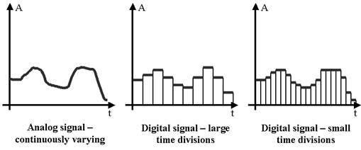
Fig. 4.2 Analog to digital conversion of signal
From the above discussion we concluded that the difference between analogue and digital information is that the analogue output is a continuous function while the digital output is a discrete number of units. The last digit of any digital number is rounded to ±0.5 of the last digit. It should also be marked that the magnitude of the digital quantity is measured only at the instant the reading is taken. One reading persists till another reading is taken (unlike the analogue quantity which is a continuous function).
4.5 Analog Measuring Device
An analog device is one in which the output or display is a continuous function of time and bears a constant relation to its input. The analog instruments find extensive use in present day applications although digital instruments are increasing in number and applications. The areas of application which are common to both analog and digital instruments are fairly limited at present. Hence, it can safely be predicted that the analog instruments will remain in extensive use for a number of years and are not likely to be completely replaced by digital instruments for certain applications.
4.5.1 Classification of analog instruments
Broadly, the analog instruments (and for that matter digital instruments) may be classified according to the quantity they measure. For example, an instrument meant for measurement of current is classified as an Ammeter while an instrument that measures voltage is classified as a Voltmeter. Thus we have wattmeters, power factor meters, frequency meters, etc. Electrical instruments may also be categorized as per the kind of current that can be measured by them, such as, direct current (d.c.), alternating current (a.c.), and direct and alternating current (d.c. / a.c.). As discussed earlier, there are three categories of instruments; on the same pattern analog instruments could also be classified as indicating, recording, integrating type.
Indicating instruments are those instruments which indicate the magnitude of a quantity being measured. They generally make use of a dial and a pointer for this purpose. Ordinary voltmeters, ammeters and wattmeters belong to this category. The analog indicating instruments may be further divided into two groups, the electromechanical instruments, and the electronic instruments. Electronic instruments are constructed by addition of electronic circuits to electromagnetic indicators in order to increase the sensitivity and input impedance.
Recording instruments give a continuous record of the quantity being measured over a specified period. The variations of the quantity being measured are recorded by a pen (attached to the moving system of the instrument; the moving system is operated by the quantity being measured) on a sheet of paper carried by a rotating drum. For example, we may have a recording voltmeter in a sub-station which keeps record of the variations of supply voltage during the day.
Integrating instruments totalise events over a specified period of time. The summation, which they give, is the product of time and an electrical quantity. Ampere hour and watt hour (energy) meters are examples of this category. The integration (summation value) is generally given by a register consisting of a set of pointers and dials.
On the basis of method used for comparing the unknown quantity (measured) with the unit of measurement the analog instruments may also be grouped into two categories of instruments:
i) Direct Measuring Instruments: These instruments convert the energy of the measurand directly into energy that actuates the instruments and the value of the unknown quantity is measured or displayed or recorded directly. The examples of this class of instruments are ammeters, voltmeters, wattmeters and energy meters.
ii) Comparison Instruments: These instruments measure the unknown quantity by comparison with a standard. The examples of comparison type instruments are d.c. and a.c. bridges.
Direct measuring instruments are the most commonly used in engineering practice because they are the most simple and inexpensive. Also their use makes the measurement possible in the shortest time.
4.6 Digital Measuring Device
A digital measuring device is that in which the value of the measured physical quantity is automatically represented by a number on a digital display or by a code, that is, a set of discrete signals. Digital measuring devices can be divided into digital measuring instruments and digital measuring transducers. Digital measuring instruments are self-contained devices that automatically present the value of the measured quantity on a digital display. Digital measuring transducers lack a digital display; and the measurement results are converted into a digital code for subsequent transmission and processing in measuring systems. The most common types of digital measuring devices are those used to measure electrical quantities, such as current, voltage, and frequency. These devices may be used to measure nonelectrical quantities—such as pressure, temperature, speed, and force—if the nonelectrical quantity is first converted into an electrical quantity. For example there are digital multimeters, digital thermometers, digital flow meters etc.
The operation of digital measuring devices is based on the digitization, that is, quantization with respect to level and coding of the value of the measured physical quantity. The coded signal is fed either to a digital display or to a data transmission and processing system. In a digital display the coded measurement result is converted into a number expressed by numerals, usually in the decimal number system. The most widely used digital displays give two to nine digits. Digital measuring instruments may use electric, cathode-ray, gas-discharge, or liquid-crystal displays.
4.7 Analogue to Digital (A/D) Conversion
The majority of present day instruments are analogue type. The importance of digital instruments is increasing, mainly because of the increasing use of digital computers in both data reduction and automatic control systems. Since digital computer works only with digital signals, any information supplied to it must be in digital form. The computer’s output is also in digital form. Thus working with a digital computer at either the input or the output, we must use digital signals.
However, most of our present day measurement and control apparatus produces signals which are of analogue nature, it is thus necessary to have both Analogue to Digital (A/D) Converters at the input to the computer and Digital to Analogue (D/A) Converters at the output of the computer.An analog-to-digital converter is a device that converts a continuous quantity to a discrete time digital representation. The reverse operation is performed by a digital-to-analog converter. Typically, an A/D is an electronic device that converts an input analog voltage or current to a digital number proportional to the magnitude of the voltage or current. However, some non-electronic or only partially electronic devices, such as rotary encoders, can also be considered ADCs. The digital output may use different coding schemes. Typically, the digital output will be a binary number that is proportional to the input, but there are other possibilities.
An analog to digital converter (Fig. 4.3) inputs an analog electrical signal such as voltage or current and outputs a binary number. In block diagram form, it can be represented as below:
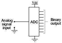
Fig. 4.3 Analog to digital converter
A digital to analog converter (Fig.4.4) on the other hand, inputs a binary number and outputs an analog voltage or current signal. In block diagram form, it looks like this:
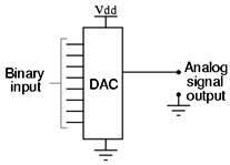
Fig. 4.4 Digital to analog converter