Module 4. Induction type indicating instruments
Lesson 10
ESSENTIALS OF Indicating Instruments
10.1 Introduction
The main purpose of any measuring system is to provide information concerning the physical variable being measured. The last stage of a measuring system is the data presentation stage,. The results of the measurement are displayed for the instant by a display device or for storage for observation at a later stage by a recorder. The data presentation devices are also known as output devices. The choice between the display devices and the recorders depend upon the information content of the output and the expected use of the output. In this section we will discuss certain features which are common to all electrical measuring instruments.
10.2 Electrical Indicating Instruments
The electrical instruments are widely used for measurement of current, voltage, resistance and power. These instruments are classified as Analog and Digital type of instruments. These principles of operation of such instruments have already been discussed in Lesson 4. The output of measuring instruments could be categorized
i) Single number output devices
ii) Time domain output devices.
The single number output devices indicate the value of the variable quantity when such values are not to be taken as a function of time, thus a single number will represent the measurement. Indicating instruments and digital display units belong to this category. A good display is one which permits the best combination of speed, sensitivity and accuracy when transferring the necessary information from the instrument to the operator. When the values of the quantity are to be taken as a function of time, the indicating instruments or digital display units do not serve this purpose. For keeping the permanent record of the variation of output with time, direct writing recorders, strip chart recorders, magnetic recorders etc. are used.
10.3 Pointer-Scale Indicating Instruments
As discussed above the analog instruments indicate the value of the measured parameter by positioning an indicator pointer on a calibrated scale. For this purpose several following arrangements can be made and the option can be exercised depending upon the requirement, feasibility and the convenience.
10.3.1 Single point indicators
This involves fixed scale and the movable pointer indicator. There are several such arrangements are available, such as, circular scale, circular scale with part circle, straight horizontal or vertical scale, arc or segmental scale etc. There could also be fixed pointer and movable scale indicators. The readability of graduated dials is influenced by shape and length of pointer, number, spacing and thickness of scale markings and size & design of numerals.
10.3.2 Multi point indicators
This type of indicators have more than one number of pointers and above each point the identification number of the medium being measured is marked. Generally this arrangement is followed in recorders.
10.3.3 Multi range indicators
Such instruments have different scales for different ranges. The choice of a particular scale is made by selector switch e.g. electrical multimeter.
10.4 Essentials of Indicating Instruments
Indicating instruments consist essentially of a pointer which moves over a calibrated scale and which is attached to a moving system pivoted in jewelled bearings. We will first consider various torques acting on its moving system. In an indicating instrument, it is essential that the moving system is acted upon by three distinct torque (or forces) for satisfactory working. The moving system is subjected to the following 3 torques:
1) Deflecting torque or operating torque
2) Controlling torque or restoring torque
3) Damping torque
10.4.1 Deflecting torque
The deflecting or operating torque (Td) is produced by utilizing one or other effects, e.g., magnetic, electrostatic, electrodynamic, thermal or inductive. The actual method of torque production depends on the type of instrument. The deflecting torque causes the moving system (and hence the pointer attached to it) to move from its zero position.
10.4.2 Controlling torque (Tc)
It is the torque which controls the movement of the pointer on a particular scale according to the quantity of the electricity, passing through it. The controlling forces are required to control the deflection or rotation and bring the pointer to zero position when there is no force, or stop the rotation of the disc when there is no power. Without such a torque, the pointer would swing over to the maximum deflected position irrespective of the magnitude of current or voltage being measured. In indicating instruments, the controlling torque, also called restoring or balancing torque, is obtained by two methods which are discussed below:
i) Spring Control
In the spring control method, a hair spring usually of phosphor bronze, attached to the moving system is used. With the deflection of the pointer, the spring is twisted in the opposite direction. This twist in the spring produces restoring torque which is directly proportional to the angle of deflection of the moving system. The pointer comes to a position of rest (or equilibrium) when the deflecting torque (Td) and the controlling torque (Tc) are equal. For example in permanent magnet moving coil type of instruments, the deflection torque is proportional to the current passing through them.
Td a I
And for spring control Tc a q
As Tc = Td
q a I
Since deflection q is directly proportional to current I, the spring-controlled instrument have a uniform or equally-spaced scales over the whole of their range.
ii) Gravity Control
Gravity control is obtained by attaching a small adjustable weight to some part of the moving system such that the two exert torques in the opposite directions.
As shown in the figure, the controlling or restoring torque is proportional to the sine of the angle of deflection, i.e., Tc a Sin q.
The degree of control is adjusted by screwing the weight up or down the carrying system.
If Td a I
Then for position of rest
Td = Tc
Or I a Sin q
Hence in gravity control instruments, the scales are not uniform but are cramped or crowded at their lower ends.
10.4.3 Damping torque
Damping torque is one which acts on the moving system of the instrument only when it is moving and always opposes its motion. Such damping force is necessary to bring the pointer to rest quickly, otherwise due to inertia of the moving system, the pointer will oscillate about its final deflected position for quite some time before coming to rest in the steady position. The degree of damping should be adjusted to a value which is sufficient to enable the pointer to rise quickly to its deflected position without over-shooting.
The damping force can be produced by i) air friction, ii) eddy currents, and iii) fluid friction. The method of air-friction damping is shown in the figure 10.1
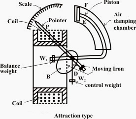
Fig. 10.1 Air-friction damping
The light aluminium piston attached to the moving system of the instrument is arranged to travel with a very small clearance in a fixed chamber closed at one end. The cross-section of the chamber is either circular or rectangular. Damping of the system is affected by the compression and suction actions of the piston on the air enclosed in the chamber. In another method, light aluminium vane is mounted on the spindle of the moving system which moves in air or in a closed sector-shaped box. Fluid-friction is similar is action to the air-friction. Due to greater viscosity of the oil, the damping is more effective. However, oil damping is not much used because of several disadvantages such as objectionable creeping of oil, the necessity of using the instrument always in vertical position and its obvious unsuitability for use in portable instruments.
Eddy current damping is the most efficient type of damping and shown in figure 10.2
Fig. 10.2 Eddy-current damping
A thin disc of a conducting but non-magnetic material like copper or aluminium is mounted on the spindle. The disc is so positioned that its edges, when in rotation, cut the magnetic flux between the poles of a permanent magnet. Hence eddy currents are produced in the disc which flow and so produce a damping force in such a direction as to oppose the very cause producing them (Lenz’s law). Since the cause producing them, is the rotation of the disc, these eddy currents retard the motion of the disc and moving system as a whole.