Module 4. Induction type indicating instruments
Lesson 11
Principle of Induction type Instruments
11.1 Working Principle of Induction Type Instruments
Consider an aluminum disc placed the between the pole of an electromagnet, as shown in fig. 11.1. Let the flux produced by flow of current of I Amperes through the coil be F and this flux will lag behind I, by a small angle β as shown in vector diagram.
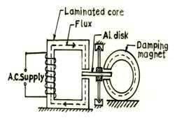
Fig.
11.1 Working principle of induction type instruments
Fig. 11.2 Vector diagram
Since the aluminum disc
act as a short circuited secondary of the transformer, therefore, an e.m.f., (say e volts) lagging behind the flux F by ![]() radians will be induced in it. As a result of
this induced e.m.f., the eddy current (I’) starts
flowing in the disc. Since the disk is purely resistive therefore the eddy
current will be in phase with induced e.m.f. (e) will
lag behind the main flux F by
radians will be induced in it. As a result of
this induced e.m.f., the eddy current (I’) starts
flowing in the disc. Since the disk is purely resistive therefore the eddy
current will be in phase with induced e.m.f. (e) will
lag behind the main flux F by ![]() radians. As the component of eddy current
(I’) along flux F is zero, therefore
torque produced is zero. It can be proved as follows.
radians. As the component of eddy current
(I’) along flux F is zero, therefore
torque produced is zero. It can be proved as follows.
Let the instantaneous values of flux and eddy current be given by F = Fmax Sin θ and i = Imax Sin (θ – α). Where α is the phase angle between the induced eddy current and flux (F).
Instantaneous torque α F i
![]()
![]()
![]()
![]()
α Fi Cos α
Where F and i are r.m.s. values.
Since in single phase
induction type instruments the angle α between main flux F and eddy current I’ is ![]() and Cos
and Cos ![]() is zero, therefore torque produced is zero.
Hence to obtain the resultant torque it is necessary to produce an eddy current
which is either appreciable less than or appreciable more than
is zero, therefore torque produced is zero.
Hence to obtain the resultant torque it is necessary to produce an eddy current
which is either appreciable less than or appreciable more than ![]() radians, out of phase with the flux which it
reacts. Several arrangements are possible but here we will discuss about the
descriptions of the two of these.
radians, out of phase with the flux which it
reacts. Several arrangements are possible but here we will discuss about the
descriptions of the two of these.
11.2 Pole Shaded Method
As shown in Fig. 11.3, in this method, the working current is passed through the coil of an electromagnet which has an air gap in one limb. Permanent magnet is used for providing damping torque. The aluminum disc is mounted on pivots and jewel bearings.
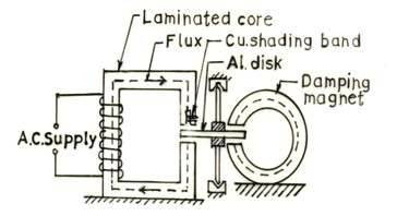
Fig. 11.3 Pole shaded method
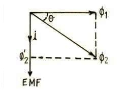
Fig. 11.4 Vector diagram
Two spiral springs are employed to provide controlling torque, wounded in direction opposite to each other if the instrument is used as Voltmeter, Ammeter and Wattmeter etc. One half of the pole face is surrounded by a copper band in order to split the working flux into two different paths. The copper shading band acts as a single turn short circuited secondary winding of the transformer. The spiral springs, pointer and scale etc. have been omitted for simplicity.
11.2.1 Theory
Let the total flux produced in the magnetic core be F Weber. Due to shading of pole, this flux will split up into two fluxes i.e. flux through un-shaded portion and other through the shaded portion. Suppose the flux F1 be the flux of the shaded portion of the pole. This flux F1 will induce an e.m.f. in the copper ring, which will lag the flux F1 by 90°, as shown in Fig. 11.4. The induced e.m.f. will force a current say i to flow in the copper ring which will be lagging behind the flux F1 by 900. The current flowing in the copper ring will produce its own magnetic field say F’2 in phase with current i. The flux given by the shaded portion of the pole will be the vector sum of F1 and F’2 which is equal to F2 lagging behind flux F1 by an angle θ and its value should be 400 to 600 for producing effective deflecting torque.
Let the flux F1 and F2 are the fluxes passing through the shaded and un-shaded portions of the pole respectively induce e.m.fs. e1 and e2 in the disc, each of which is 900 in phase behind the fluxes responsible for inducing it. These induced e.m.fs; will induce eddy currents (say i1 and i2) in the disc lagging by a small angle (say α) behind its voltage due to the inductance of the path in the disc.
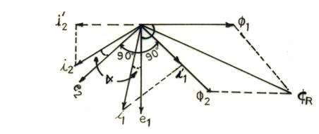
Fig. 11.5 Vector diagram
From Fig. 11.5, it is obvious that each of the current i1 and i2 has a component in phase with the other flux such i1′ and i2′. Hence two torques are acting in a directions having angle θ are produced in the instrument. Resultant of these two torques, provides an operating or deflecting torque.
11.3 Two Pole Method
This method is also known as split phase method. In this method, two laminated magnets A and B are placed near to each other with aluminum (Al) disc in between and a non inductive resistance R is connected in series with the magnetizing coil of magnet A and an inductive coil L is connected in series with the magnetizing coil of magnet B, as shown in Fig. 11.6.
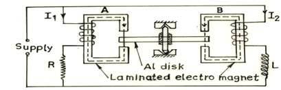
Fig. 11.6 Two pole method (split phase)
Hence there will be two fluxes having phase difference of less than 90° with each other, acting on the disc which will produce a resultant torque in the aluminium disc.
Let the flux produced by the magnet A and B is F1 and F2 respectively. F2 is lagging F1 by an angle θ as shown in Fig. 11.5. Hence an operating or deflecting torque will be produced as explained above in case of shaded pole method.