Module 4. Induction type indicating instruments
Lesson 12
Induction type Voltmeter and Ammeter
12.1 Shaded Pole Type Voltmeter
A volt meter is an instrument used to measure the potential difference between the two points in an electric circuit. In analog voltmeters, the pointer moves over a calibrated scale in proportion to potential difference across the points where as in case of digital voltmeters, it displays numerical values with the help of analog to digital converter. The induction type voltmeter operates on the either shaded pole method or on two pole method’s working principle as explained in Lesson 11.
Fig. 12.1 Shaded pole type voltmeter
A non inductive high resistance is also inserted in series with the shunt coil and is connected across the supply, whose potential difference has to be measured. Since the voltmeters are connected across the supply, so the current flowing through coil is very small of the order of 5 to 10 mA. The spindle of aluminum disc is provided with a pointer moving over a calibrated scale in terms of voltage. Spiral springs are provided on both the ends of spindle for providing controlling torque. Permanent magnet (C- magnet) is used to provide damping torque on the spindle. As the instrument is provided with spiral springs, to provide controlling torque, the scale of the instrument is uniform because in such instrument this torque is directly proportional to angle of deflection of the pointer. Spiral springs, pointer and damping magnets are omitted for clear understanding of the figure. For detail working of the instrument, please refer to working principle of induction type instruments described in Lesson 11.
12.2 Split Phase Ammeter
An ammeter is always connected in series with load current directly or through CT (Current Transformer). As shown in Fig. 12.2, both the windings on the two laminated electromagnets A and B are connected in series but winding is shunted by a resistance R with the result of which, the current in this winding lags with respect to the total current (I). Hence the necessary phase angle (α) required between two fluxes is produced by the laminated electromagnets A and B.
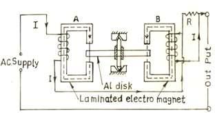
Fig. 12.2 Split phase induction type ammeter
The operating principle of the induction type instrument is based on the two pole method as discussed in Lesson 11. Two fluxes produced by laminated magnet A and B are focused upon the aluminum disc, having a phase angle between them required for producing a resultant torque in the spindle of the moving system. Being a spring control based controlling torque, the scale is uniform and the deflecting torque is directly proportional to square the load current. Eddy current damping is used to provide necessary damping torque by a permanent magnet. Spiral springs, pointer and damping magnets are omitted for clear understanding of the Fig. 12.2.
12.3 Advantages and Disadvantages of Induction Type Instruments
Advantages
(a) Damping is very much effective and efficient.
(b) Full scale deflection more than 200° can be obtained.
Disadvantages
(a) Power consumption is large and hence not recommended where continuous monitoring of ac quantities is required.
(b) Variation in temperature and frequency may cause serious errors if necessary compensations are not provided.
(c) As these instruments are based on principle of induction, they can be used on AC supply only.
12.4 Compensation for Frequency and Temperature Errors
12.4.1 Compensation for variation in frequency
Variation in frequency causes serious errors because deflecting torque is directly proportional to frequency and also the value of impedance (Z) and Cos α depends upon the supply frequency. The error is compensated by use of non inductive shunt in case of an Ammeter, when the frequency increases, the increase in impedance of the winding cause a greater proportion of the total current to flow in the non inductive shunt (whose impedance remains constant for all frequency) and lesser proportion of the total current in flow in the winding and to an extent thus compensate the increase in torque (since T α. f).
In case of voltmeter, the impedance of the winding increases with the increase in frequency, hence smaller current is drawn by the winding, which tends to compensate the increase in torque due to increase in frequency.
12.4.2 Compensation for variation in temperature
Variation in temperature changes the resistance of the eddy current paths, therefore, may result in serious errors. The error is compensated in case of an ammeter, employing a shunt of material having a high temperature coefficient of resistance than the material of the disc. This shunt may be the same one as used for frequency compensation. When the temperature increases, the resistance of the shunt increases, hence the greater portion of the current flows through the coil and decreases in torque due to smaller eddy current in the disc owing to increase in resistance at high temperature is compensated. The combination of shunt and swapping resistance in series with the instrument is often employed to compensate the temperature error in case of voltmeters. Since the frequency errors in induction type instruments are so serious that cannot be compensated satisfactorily. Hence these instruments are used for only constant frequency supplies or where the fluctuation in frequency is very small.