Module 4. Induction type indicating instruments
Lesson 13
Induction type Wattmeter, Watt-hour meter, AND Dynamometer type Power factor meter
13.1 Induction Type Wattmeter
These types of watt-meters operate on the same working principle on which the induction type ammeter and voltmeter operates. These instruments can only be used on ac supply while dynamo-meter type watt meters can be used on either ac or dc supply system. Induction type watt-meters are useful only when the supply and frequency remains constant. Since both the coils i.e. current coil and pressure coils are necessary in such instrument, it is not essential to use shaded pole principle. Because for producing a deflecting torque, two fluxes are essential with suitable phase angle and it would be available from these two coils.
13.1.1 Construction
A watt-meter has two laminated electromagnet, one of which is excited by load current or definite fraction of it, and is connected in series with the circuit, known as series magnet and the other is excited by the current proportional to the applied voltage or fraction of it and is always connected across the supply, known as shunt magnet. An aluminum disc is so mounted so that it cuts the fluxes produced by both the magnets. As a result of which, two e.m.f’s are produced which induces two eddy currents in the disc. C - Magnet is used to provide necessary damping torque to the pointer, to damp out the oscillations. Deflecting torque is produced due to interaction of these eddy currents and the inducing flux. Copper shading bands are provided either on central limb or on the outer limb of the shunt magnet, and can be so adjusted as to make the resultant flux in the shunt magnet lag behind the applied voltage by 90°. Both the watt-meters are provided with spiral springs A and B, for producing controlling torque to counter balance the deflecting torque. In Fig. 13.2 the spiral spring and damping magnet is omitted for simplicity. The scale of such type instruments is quite uniform and extends over an angle of 300°. Currents up to 100 A can be handled by these watt-meters directly where as beyond this current transformers are used. Two types of induction type watt meters are available. Line diagrams of both of the types are detailed in Fig. 13.1 and 13.2.
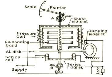
Fig. 13.1 Induction type wattmeter
In the form of the instrument shown in Fig. 13.1, two pressure coils are connected in series in such a way that both of them send flux through the central limb. The series magnet also carries two small current coils connected in series and wound so that they magnetized their respective cores in the same direction. Correct phase displacement between the fluxes produced by series and shunt magnet is obtained by the adjustment of copper shading band on the central limb.
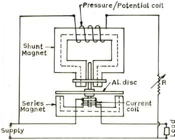
Fig. 13.2 Induction type wattmeter
In Fig. 13.2, there is only one pressure and one current coil. Two projecting poles of shunt magnet are surrounded by a copper shading band whose position can be adjusted for correcting the phase of the flux of this magnet with the applied voltage. The pressure coil circuit of induction type instrument is made as inductive as possible so that the flux of the shunt magnet may lag nearly by 90° behind the applied voltage.
13.1.2 Advantages
The advantages of induction watt meters are the same as those of induction ammeters – long scale, freedom from effects of stray field, and have effective damping torque.
13.1.3 Disadvantages
Following are the disadvantage of the induction type instruments:
a) Change in temperature causes variation in the resistance of the moving element, affects the eddy currents therein, and so the operating torque. The error due to this is in part offset by a balancing effect due to change in temperature of the windings.
b) Change in frequency from that of the calibration value causes variations in both the reactance of the voltage coil circuit, which is highly inductive, and also in the amount of compensation from the phase – compensating circuit. Within the limits of frequency variation met within practice on the mains, this last error in not important.
13.2 Induction Type Single Phase Watt Hour Meter
A watt hour meter is used to sum up the total energy consumed by a consumer during a period so that it can be charged for the actual energy consumed. The working principle, theory and advantage / disadvantages are almost similar to single phase watt meter. The construction of single phase watt hour meter is also almost similar to single phase induction type watt meter as discussed above. The pointer and spiral springs are replaced by wheel-train mechanism for summing up of total energy consumed where as the damping magnet is replaced by braking magnet. The construction of this type of watt hour meter is shown in Fig. 13.3.
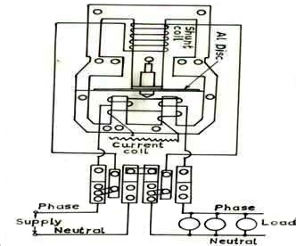
Fig. 13.3 Induction type energy meter
The brake magnet and recording wheel-train being omitted for clear understanding of the diagram. The description of registering mechanism and braking system is detailed below.
13.2.1 Registering or counting system
The registering or counting system essentially consists of gear train, driven either by worm or pinion gear on the disc shaft, which turns pointers that indicate on dials the number of times the disc has turned. The energy meter thus determines and adds together or integrates all the instantaneous power values so that total energy used over a period is thus known. Therefore, this type of meter is also called an ‘integrating meter’.
13.2.2 Braking system
Braking of the disk is provided by a small permanent magnet, located diametrically opposite to the alternating current magnets. The disk moves between the magnet’s gaps. The movement of rotating disc through the magnetic field crossing the air gap sets up eddy currents in the disc that reacts with the magnetic field and exerts a braking torque. By changing the position of the brake magnet or diverting some of the flux therefore, the speed of the rotating disc can be controlled. Creep error can be rectified by drilling a small hole in the aluminum disc passing through the magnetic flux of braking magnet.
13.3 Errors and Adjustment in Induction Type Instruments
13.3.1 Phase and speed error
It is necessary that the energy meter should give correct reading on all power factors, which is only possible when the field set up by shunt magnet flux lags behind the applied voltage by 90°. Ordinarily the flux set up by shunt magnet does not lag behind the applied voltage exactly by 90° because of winding resistance and iron losses. The flux due to shunt magnet is made to lag behind applied voltage by 90° with the help of copper shading band provided on the central limb. An error due to incorrect adjustment of shading band will be evident when the meter is tested on a load of power factor less than unity.
An error on the fast side under these conditions can be eliminated by bringing the shading band nearer to the disc and vice versa. An error in the speed of the meter when tested on non inductive load can be eliminated by adjustment of the position of the brake magnet. Movement of the brake magnet in the direction of the spindle will reduce the braking torque and vice versa. Speed of disc is directly proportional to the distance between the disc and brake magnet.
13.3.2 Friction compensation
The two shading bands embrace the flux contained in the two outer limbs of the shunt electromagnet, and thus eddy current are induced in them which cause a phase displacement between the enclosed flux and main gap flux. As a result, a small driving torque is exerted on the disc, this torque being adjusted, by variation of the position of these bands, to compensate for frictional torque in the instrument.
In some energy meter, it is observed that the disc continue to rotate even when the load on the energy meter is zero and potential coil is in excited condition. This defect is known as creeping and is prevented by cutting two holes or slots in the disc on opposite sides of the spindle. The disc tends to remain stationary when one of the holes comes under one of pole of the shunt magnet. In some cases, a small piece of iron wire is attached to the edge of the disc. The force of attraction of the brake magnet upon this wire is sufficient to prevent continuous rotation of the disc under no load condition.
13.3.3 Temperature and frequency errors
The error due to variation in temperature is very small. Since the various effects due to change in temperature tends to neutralize each other on unity power factor if not on low power factor (lagging). Since the meters are used normally on fixed frequency and hence these can be adjusted to have a minimum error at declared supply frequency which is normally 50 cycles / second.
13.4 Single Phase Dynamo-meter Type Power Factor Meter
The power factor meter is used to indicate the instantaneous power factor of the consumer. It consist of two fixed coils CC connected in series carrying the load current (or a definite fraction of it) and two identical moving coils P1 & P2 wound with a fine copper wire, fixed at right angle to each other and pivoted on the same spindle. The pressure coils P1 and P2 move together and carry a pointer, which indicates the power factor of the circuit directly on the scale.
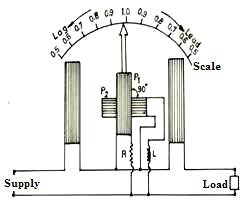
Fig. 13.4 Dynamometer type power factor meter
The pressure coil P1 is connected across the supply through a non inductive resistance R and pressure P2 is connected across the supply through a highly inductive choke coil of inductance L. The value of non inductive resistance R and inductance L are so chosen that for the normal frequency, the current in the two pressure coil P1 and P2 is same. Thus these coils P1 and P2 produce equally strong magnetic field displaced by 900 in space as well as in the phase. For measurement of power factor on high voltage system, the current and pressure coils of the instrument may be connected to the main circuit through current and potential transformer respectively.
13.4.1 Theory
While measuring power factor of an installation, there may be three possibilities of installation’s power factor, which are described here:
(a) Power Factor is Unity: When the circuit is switched on, the current in the potential coil P1 will be in phase with current in coils CC, where as the current in pressure coil P2 will lag 900 behind the voltage or behind the current in the circuit coli CC. Thus pressure coil P1 will experience a turning moment so its plane will come in a position parallel to a plane of a current coil CC. The average torque on coil P2 will be zero but being mechanically coupled to coil P1, it will follow the rotation of coil P1. Hence the pointer will in the centre of the calibrated scale and it will show the power factor as unity. The position of coil P1 is shown in Fig. 13.4 and it will maintain the reading till the load current is in phase with the voltage.
(b) When Power Factor is Zero (lagging): In this situation, the current flowing in the pressure coil P2 will be in phase with load current flowing in the fixed current coil CC, both lagging behind the applied circuit voltage by 900 and current in pressure coil P1 will lead the load current in current coil CC by 900. Thus only pressure coil P2 will experience a turning moment so its plane will come in a position parallel to the plane of current coils CC. At this instant, the pointer will indicate zero power factor lagging.
(c) When Power Factor Zero (leading): When the current flowing in fixed coils CC leads the applied voltage by 90° and, therefore, the field of pressure coils P1 by 90° and that of coil P2 by 180°. Hence the polarity of field in current coils is the reverse of that considered above. At this instant, the pointer will indicates the power factor as zero leading on the other half of the scale.
For an intermediate power factor, the moving system takes up intermediate position and the pointer makes an angle of (90°- F) with the axis of the fixed coils where F the phase angle between load current is and applied voltage of the load circuit.