Module 5. Transducers
Lesson 14
Introduction to sensors and transducers
14.1 Introduction
In a measurement system all the quantities being measured, could not be displayed as such. In such situation, the accurate measurement of a quantity is usually done by converting the related information or signal to another form which is more conveniently or accurately displayed. This is achieved with the help of a device which is known as transducer.
A sensor senses the condition, state and value of the process variable which reflects the output of the instrument. The transducer is a device which provides a usable output in response of corresponding input, which may be physical or mechanical quantity, property or condition. More precisely, ‘A TRANSDUCER is a device, which transforms energy from one form to another’. The transducer may be mechanical, electrical, magnetic, optical, chemical, thermal nuclear, acoustic, or a combination of among of two or more.
All forms of transducers have some merits and demerits but most of the shortcomings have been overcome with the introduction of electrical transducers. The most instrumentation systems having ‘Non-Electrical’ input quantity and this non-electrical quantity is generally converted into an electrical form by a transducer.
14.2 Basic Requirements of Transducer
The following are the basic requirements of a good quality transducer:
a) Ruggedness
b) Linearity
c) No hysteresis
d) Repeatability
e) High output signal quality
f) High reliability and stability
g) Good dynamic response
h) No deformation on removal of input signal
14.3 Classification of Transducers
The transducers could be classified in several ways. This classification could be on the basis of their application, method of energy conversion, the nature of signal output and according to whether they are self generating or the externally powered units. The transducers can be broadly classified as:
1) Primary transducers and Secondary transducers.
2) Analog transducers and Digital transducers.
3) Active transducers and Passive transducers.
4) Transducers and Inverse transducers
14.3.1 Primary transducers and secondary transducers
The transducer that directly senses the input signal and converts the physical property into the electrical signal is called primary transducer or a sensor. ‘Thermistor’ is an example of primary transducer. It senses the temperature directly and causes the changes in its resistance with respect to temperature.
On the other hand, if the input signal is sensed first by some detector or sensor and its output, which may be of some other form than the input signal, is given as input to another transducer for conversion into electrical form, then such a transducer is called as secondary transducer.
14.3.2 Analog transducers and digital transducers
The output from the transducer may be a continuous function of time or it may be in discrete function of time. On this basis the transducers may be classified into two categories.
A transducer, which converts input signal into output signal in a continuous function of time is known as Analog transducer. Linear variable differential transformer (LVDT), thermo-couple are the examples of Analog Transducer.
On the other hand, a transducer, which converts input signal into output signal in the form of pulses i.e., it gives discrete output is called a digital transducer. The digital transducers are becoming very popular and useful because the digital signals can be transmitted over a long distance, with minimum distortion due to amplitude variation and phase shift.
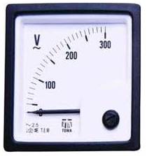
Fig.
14.1 (a) Analog voltmeter
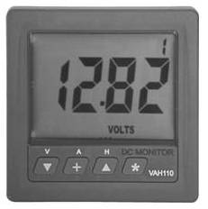
Fig.
14.1 (b) Digital voltmeter
14.3.3 Active and passive transducers
On the basis of methods of energy conversion used the transducers are classified in to following two categories:
A transducer, which develops its output in the form of electrical current or voltage without any auxiliary source, is called active transducer or the self generating transducers. The energy required for this is absorbed from the physical phenomenon which is being measured. This type of transducer draws energy from the system under measurement. Examples are thermocouples, piezo-electric transducers, photovoltaic cell etc. Such transducers normally give very small output and so amplification of the signal becomes essential.
Externally powered transducers are those which derive the power required for energy conversion from an external power source. An electrical transducer, in which electrical parameter like resistance, inductance or capacitance changes with change in the input signal, is called as a passive transducer. They may also absorb a little power from the process variable being measured. Resistive, inductive and capacitive transducers viz., potentiometric devices, differential transformer etc. are known as passive transducers.
14.3.4 Inverse transducers
A transducer is generally defined as a device which converts a non electrical quantity into an electrical quantity. An inverse transducer is a device which converts an electrical quantity into a non-electrical quantity.
A current carrying coil moving in a magnetic field is an inverse transducer, because current by it is converted into a force, which causes translational or rotational displacement. A most useful application of inverse transducers is in feedback measuring systems.
An actuator is an inverse transducer as it is having an electrical input and a low-power non-electrical output. A piezo-electric crystal also acts as an inverse transducer because when a voltage is applied across its surfaces, it changes its dimensions causing a mechanical displacement.
14.4 Characteristics of Transducers
Performance criteria of the transducers are based upon certain set of characteristics that gives a meaningful description of quality of measurement. Normally these characteristics of a measurement system are those that must be considered when the system or instrument is used. All these characteristics have to be taken into account, when choosing a transducer for any application.
The characteristics of transducers are described as:
A) Input characteristics
B) Transfer characteristics
C) Output characteristics
14.4.1 Input characteristics
i). Type and Operating Range of Input Quantity: The first consideration for the selection of a transducer is the input quantity which is to be measured and its range of operation. The type of input quantities is generally known in advance. The useful operating range of transducer is an important factor in the choice of a transducer for a particular application. The maximum value or the maximum limit is decided by the transducer capabilities, whereas, the minimum value of range or the lowest limit is normally determined by the unavoidable noise which may originate in the transducer during measurement.
A good resolution is required throughout its operating range of a transducer.
ii). Loading Effects: In an ideal transducer, there is no loading effect on the input quantity being measured by the transducer. However, practically it may not be possible. The magnitude of the loading effects is expressed in terms of force, power or energy obtained from the input quantity. Hence the transducer which is selected for a particular application should ideally extract no force, power from the input quantity.
14.4.2 Transfer characteristics
The transfer characteristics involve three separate elements:
i). Transfer function
ii). Sensitivity
iii). Error.
i) Transfer Function: It is defined as relationship between the input quantity and output and describes the input and output behaviour of the system.
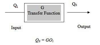
Where, Q0 and Qi are respectively output and output of the transducer.
ii) Sensitivity: The sensitivity of a transducer is the ratio of change in output for a given change in input
![]()
In general, the sensitivity of transducers is not constant and is dependent upon the input quantity (Qi). In some cases the relation between output and input becomes linear.
If the sensitivity is constant over the entire range of the transducer it shall be defined as :
![]()
The inverse of sensitivity is called scaled factor.
![]()
iii) Error: Many a times the input-output relationship given by Q0 = GQi is not followed by transducer. In such cases, error is obtained in transducers.
Let at a particular input Qi, ideally the output will be Q0
but practically an output ![]() is obtained, then the error
of the instrument is:
is obtained, then the error
of the instrument is:
![]()
The error could be due to any of the followings:
a) Scale error.
b) Dynamic error.
c)
Error
on account of noise and drift.
a) Scale Error: There are four different types of scale errors:
i). Zero Error: In such type of error, the output deviates from the original value by a constant factor over the entire range of the transducer.
ii). Sensitivity Error: This type of error occurs where the observed output deviates from the correct value by a constant value.
iii). Hysteresis: The effect of hysteresis is obtained in all transducers. The output of a transducer not only depends upon the input but also upon input quantities previously applied to it. So, different output is obtained when the same value of input quantity is applied, depending upon whether it is increasing or decreasing.
iv). Non-Conformity: When experimentally obtained transfer function deviates from the theoretical transfer function for almost every input
b) Dynamic Error: This type of error occurs when the input quantity is varying with time. This type of error occurs where system contains energy storage element and due to this the output cannot follow input exactly. The dynamic error can be made small by having a small time constant.
c) Noise and Drift Error: Noise and drift signals originating from the transducers very with time and are superimposed on the output signal.
d) Error due to Change of Frequency: A sine wave input in a linear transducer, a sine wave output obtained, as the frequency of the sine wave input is increased, the transducer is required to respond more and more quickly. In this process beyond the range of a particular frequency the transducers can no larger respond with respect to its sinusoidal input is changing. Therefore the output of the transducer becomes smaller as well as the phase shift between the input and output increases. Hence the frequency increases the output of the transducer decreases.
14.4.3 Output characteristics
The output characteristics of a transducer are considered as given below :
i). Type of electrical output.
ii). Output impedance.
iii). Useful output range.
i). Type of Electrical Output: The output of transducer may be a voltage, current impedance or a time function of these amplitudes. The above quantities may or may not be acceptable to the latter stages of the instrumentation system. There is possibility to change their magnitudes or change in their format by signal conditioning equipment for making them drive the different stages of instrumentation system.
ii). Output Impedance: In ideal transducer the value of the output impedance should be zero, but practically it is not possible and, therefore, its value should be kept as low as possible to minimize the loading effects. The output impedance gives the information of amount of power than can be transferred to the further stages of the instrumentation system for a given output signal level. The value of output impedance is low compared to the forward impedance of the system, the transducer behaves as a constant voltage source (provided a voltage is the output of transducer), when the forward impedance is high as compared to the output impedance of transducer, it behaves as constant current source.
iii). Useful Output Range: The output range of a transducer is limited by noise signal at the lower end which may shroud the required input signal. The output range can be increased by adding of amplifier in the transducer in some cases. The addition of amplifier also increases the noise level and therefore in such situation the amplifier should be avoided.
14.5 Factors Affecting the Choice of Transducers
The following is the summary of the factors influencing the choice of a transducer for measurement of a physical quantity:
1. Operating Principle: The transducers are so many times selected on the basis of operating principle used by them. The operating principles used in transducer may be resistive, inductive, capacitive, opto-electronic, piezoelectric and so on.
2. Sensitivity: The transducer should give a sufficient output signal per unit of measured input in order to yield meaningful data.
3. Operating Range: The transducer should maintain the range requirements and have a better resolution over its entire range.
4. Accuracy: High degree of accuracy is necessary for measurement.
5. Error: The errors inherent in the operation of the transducer itself, but it should maintain the expected input-output relationship as described with its transfer function so as to avoid errors.
6. Transient and Frequency Response: The transducer should meet the desired time domain specifications as well as it should ideally have a flat frequency response curve.
7. Loading Effects: To avoid loading effect, it is necessary that a transducer has a high input impedance and a low output impedance.
8. Physical Environment: The
transducer selected should be able to work under specified environmental
conditions and maintain its output-input relationship