Module 5. Transducers
Lesson 15
Mechanical Input Transducers
15.1 Introduction
A generalized mechanical system consists of a sensing element which responds directly by reacting to the measurand and a transducing element which is responsible for conversion of measurand into analogous driving signal. The sensing element may also serve to transducer the measurand and put it into more convenient form. The unit is then called as detector-transducer. Most of the detector transducer devices employ the devices such as a diaphragm, a Bourdon tube or a bellow. All of these are the elastic elements. The action of these elements is based on elastic deformation brought about by the force resulting from pressure.
15.2 Mechanical Elastic Elements
Mechanical detector-transducer elements are generally elastic elements. These units are frequently employed to furnish an indication of the magnitude of applied pressure/force through a displacement measurement. Operation of the elastic elements is based on one or the combination of following acts:
i) Compression that tends to force the molecules of the solid close together.
ii) Tension that tends to force the molecules further apart.
iii) Torsion that tends to twist the solids.
15.3 Principle of Operation of Elastic Elements
The measurement of force or pressure can be done by converting the applied force or pressure into a displacement by elastic elements which act as primary transducer. This displacement, which is a function of pressure, is then measured by other transducers which act as secondary transducers. The output of the secondary transducer becomes a function of displacement, which in turn is a function of pressure. Mechanical methods are thus used to convert the applied force or pressure into displacement. These devices are also known as Force Summing Devices.
The mechanical elastic elements possess elasticity. When deformed, the stresses developed in the summing device establish equilibrium with the pressure applied on it. As the pressure is removed the elastic element regains its original position. The choice and design of the type of force summing elements depends on the magnitude of the force or pressure to be measured.
15.4 Types of Force Summing Devices
Mechanical input transducers generally use one of the following types of force summing devices:
i) Diaphragm
ii) Bellows
iii) Bourdon tube
15.4.1 Diaphragms
The movement of diaphragm is a convenient way of sensing pressure differential. The diaphragm is a flexible disc made up of sheet metal with precise dimensions. It could be either flat or with concentric corrugations on it. The edge of the diaphragm is rigidly fixed. When the unknown pressure is applied to one side of the diaphragm, the centre of the diaphragm is displaced. This displacement which is proportional to the applied pressure is measured. Some instruments use the diaphragm as the pressure sensor, while others use it as a basic component of capsular element. The capsules consist of two diaphragms welded together at their peripheries. Evacuated capsules are used for detection of absolute pressure and single element diaphragm for highly sensitive measurement.
The sensitivity of a capsule increases in proportion to its diameter and inversely proportional to the thickness of sheet used. Multiple capsule elements can be built from the capsules. These elements are useful in increasing the output motion resulting from a pressure change.
The diaphragm pressure element, shown in Fig. 15.1 B, employs a thin flexible diaphragm of such material as brass or bronze. The non-metallic-diaphragm pressure element employs a flexible diaphragm of high quality leather or a thin neoprene-like material. ‘PEXT’ is the external pressure, ‘PREF’ is the reference pressure and ‘w’ is the deflection at the centre point of the diaphragm. The extent of this deflection depends upon the pressure applied on the diaphragm. This deflection of the diaphragm operates an indicating or recording type instrument. The resulting displacement of a diaphragm can be multiplied by a suitable linkage and a pointer is made to operate over a scale. Diaphragm gauges are normally employed for low pressure or vacuums up to about 5 psi. Differential pressure can be measured by applying the second pressure to the other side of the diaphragm and using a sealed means of detecting the motion of diaphragm as shown in Fig.15.1 A.
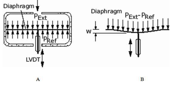
Fig. 15.1 Diaphragm pressure element
15.4.2 Bellows
The bellows pressure sensor is made of a sealed chamber that has multiple ridges like the pleats of an accordion that are compressed slightly when the sensor is manufactured. It is a thin walled tube having a corrugated shape. When pressure is applied to the chamber, the chamber will try to expand and open the pleats. Essentially it is a pressure activated spring. The stiffness or in other words the displacement for a particular pressure depends upon the type and thickness of the material used. The most commonly used material for bellows pressure sensing elements are steel, phosphor bronze and beryllium copper.
The Fig. 15.2 shows an example of a bellows sensor, which uses a spring to oppose the movement of the bellows and provides a means to adjust the amount of travel the chamber which it will have when pressure is applied. In low-pressure bellows sensors, the spring is not required. The travel of the bellows can be converted to linear motion so that a switch can be activated, or it can be connected to a potentiometer. This type of sensor is used in low-pressure applications usually less than 30 psi. The bellows sensor is also used to make a differential pressure sensor. In this application two bellows are mounted in one housing, so that the movement of each bellows opposes the other. This will cause the overall travel of the pair to be equal to the difference of pressure that is applied to them.
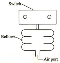
Fig.15.2 Schematic diagram of bellows pressure element
Generally, metallic bellows acting with pressure on one side and a spring on the other is used. The pressure range of the system is determined mainly by the effective area of the bellows and the spring gradient. Often the inside of the entire assembly is tinned for further protection against corrosion. Bellows gauges are generally employed for measuring gauge pressures or vacuums up to 100 psi. Precision bellows are available with minimum error due to drift, friction and elastic hysteresis. Sensitivity of bellows increases as a function of size. In general, it can be said that bellows elements will deliver high forces and can detect slightly higher pressures than the diaphragm capsules. The disadvantages of the bellows element include being subject to work hardening a sensitive to ambient temperature variations.
15.4.3 Bourdon tube
It is most widely used force summing or pressure sensing element. The device was invented by Eugene Bourdon in the year 1849. The basic idea behind the device is that, cross-sectional tubing when deformed in any way will tend to regain its circular form under the action of pressure. The Bourdon pressure gauges used today have a slight elliptical cross-section and the tube is generally bent into a Ì or C-shape or arc length of about 27 degrees. The detailed diagram of the Bourdon tube is shown in Fig. 15.3.
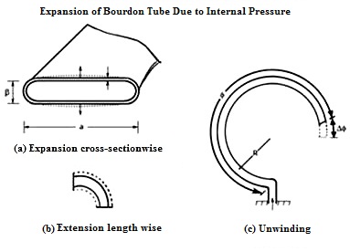
Fig. 15.3 Bourdon tube element
It consists of a narrow bore tube of elliptical cross-section Fig. 15.3 (a), sealed at one end. The pressure is applied at the other end which is open and fixed. The tube is formed into a curve, a flat spiral or a helix. When the pressure is applied, the effect of the forces is to straighten it so that the closed end is displaced.
A ‘Ì or C Bourdon tube’ as used in direct indicating gauge usually has an arc of 250°. The process pressure is connected to the fixed socket end of the tube while the tip end is sealed. As the fluid pressure enters the Bourdon tube, because of the difference between inside and outside radii, the Bourdon tube presents different areas to pressure, which causes the tube to be reformed, and because of a free tip available, this action causes the tip to travel in free space and the tube unwinds. The resulting tip-motion is non-linear because less motion results from each increment of additional pressure. This non-linear motion has to be converted to linear rotational pointer response. This travel of tip is suitably guided and amplified for the measurement of the internal pressure. But the main requirement of the device is that whenever the same pressure is applied, the movement of the tip should be the same and on withdrawal of the pressure the tip should return to the initial point.
Other than C-type, Bourdon gauges can also be constructed in the form of a helix or a spiral. The types are varied for specific uses and space accommodations, for better linearity and larger sensitivity. For thorough repeatability, the bourdon tubes materials must have good elastic or spring characteristics. The surrounding in which the process is carried out is also important as corrosive atmosphere or fluid would require a material which is corrosion proof. The commonly used materials are phosphor-bronze, silicon-bronze, beryllium-copper, and other C-Cr-Ni-Mo alloys. Like all elastic elements a bourdon tube also has some hysteresis in a given pressure cycle. By proper choice of material and its heat treatment, this may be kept to within 0.1 and 0.5 percent of the maximum pressure cycle.
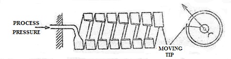
Fig. 15.4 Helical bourdon element
Figure 15.4 shows the construction of a helical Bourdon element. This sensor produces a greater motion of the free end eliminating the need for amplification. Other advantages of this design include the high over range protection available, for example, a 0 to 1000 psig element man safely be exposed to 10,000 psig pressure and it suitable for pressure measurement on continuously fluctuating services. Helical elements can also be used as the element in differential pressure sensors if one of the pressures is acting on the outside surface and the other on the inside of the coil.
The displacement created by the action of the elastic deformation element may also be converted into a change of some electric parameter. The force summing member actuates a transducer which converts the displacement into an output of electrical format. The resistive and inductive transducers have been successfully used as secondary transducers along with a diaphragm for measurement of pressure. Linear Variable Differential Transformer (LVDT) is used as a secondary transducer for measurement of pressure with bellows or Bourdon tube acting as a primary transducer. The pressure is converted into displacement which is sensed by LVDT and transduced into a voltage.