Module 5. Transducers
Lesson 16
Electrical Transducers: Resistive transducers
16.1 Introduction
The electrical measurements are used for measurement of electrical quantities but its use in measurement of non electrical quantities is growing. In the measurement of non electrical quantities a detector is used which usually converts the physical quantity in displacement. The displacement actuates an electric transducer, gives an output which is electrical in nature. The electrical quantity so produced is measured by standard methods used for electrical measurements. The resultant electrical output gives the magnitude of the physical quantity being measured. The advantages and limitations of electric measurements have been presented in Lesson 3.
The electrical signal could be a voltage, current or frequency. The production of these signals is based upon the resistive, inductive or capacitive effects. These phenomena may be combined with appropriate primary sensing elements / detectors to produce different types of transducers.
16.2 Resistive Transducers
The resistive transducers or resistive sensors are also called as variable resistance transducers. The variable resistance transducers are one of the most commonly used types of transducers. They can be used for measuring various physical quantities, such as, temperature, pressure, displacement, force, vibrations etc. These transducers are usually used as the secondary transducers, where the output from the primary mechanical transducer acts as the input for the variable resistance transducer. The output obtained from it is calibrated against the input quantity and it directly gives the value of the input.
The variable resistance transducer elements work on the principle that the resistance of the conductor is directly proportional to the length of the conductor and inversely proportional to the area of the conductor.
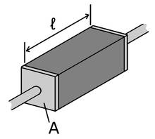
Fig. 16.1 Resistance element
Thus, if ‘L’ is the length of the conductor (m) and ‘A’ is its area (m2) as shown in Fig.16.1, then its resistance ‘R’ (ohms) is given by:
R = ρL/A
Where ‘ρ’ is called as resistivity of the material measured in ‘ohm-m’ and it is constant for the given material.
Some of the popular variable resistance transducers that are being used for various applications are as below:
16.2.1 Sliding contact devices
In the sliding contact type of variable resistance transducers, there is a long conductor whose effective length is variable. One end of the conductor is fixed, while the position of the other end is decided by the slider or the brush that can move along the whole length of the conductor. The slider is connected to the body whose displacement is to be measured. When the body moves the slider also moves along the conductor so its effective length changes, due to which it resistance also changes. The effective resistance is measured as the resistance between the fixed position of the conductor and the position of the sliding contact as shown in Fig. 16.2. The value of the resistance is calibrated against the input quantity, whose value can be measured directly. One of most popular sliding contact type of variable resistance transducer is the potentiometer. These devices can be used to measured translational as well as angular displacement and are shown in Fig 16.2 and 16.3.
Fig. 16.2 Sliding contact type of variable resistance element
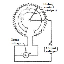
Fig. 16.3 Rotational potentiometer
16.2.2 Wire resistance strain gauge
The strain gauge is a fine wire which changes its electric resistance, when mechanically strained. When an electrical conductor is stretched within the limits of its elasticity such that it does not break or permanently deform, it will become narrower and longer, changes that increase its electrical resistance end-to-end. Conversely, when a conductor is compressed such that it does not buckle, it will broaden and shorten in size, the changes that decrease its electrical resistance end-to-end. A typical strain gauge arranges a long, thin conductive strip, as shown in Fig. 16.3 (a), made in a zigzag pattern of parallel lines such that a small amount of stress in the direction of the orientation of the parallel lines results in a multiplicatively larger strain over the effective length of the conductor Fig. 16.3 (b). The change in resistance of a strain gauge can be measured using a Wheatstone bridge.
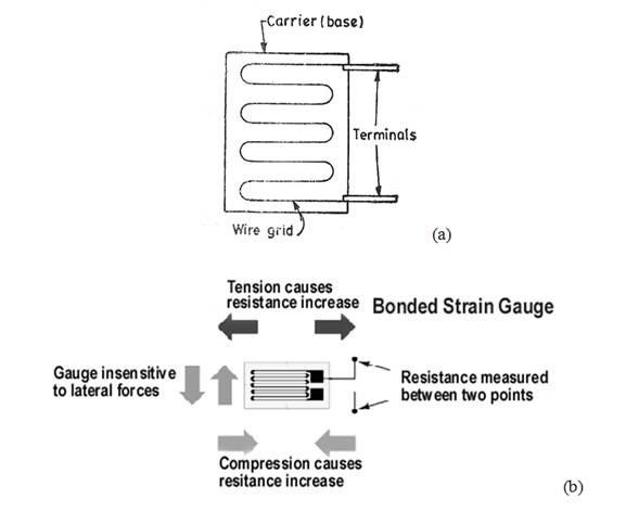
Fig. 16.4 Working principle of strain gauge
A fundamental parameter of the strain gage is its sensitivity to strain. It is expressed quantitatively as the gauge factor (GF). Gauge factor is defined as the ratio of fractional change in electrical resistance to the fractional change in length (strain). The gage factor for metallic strain gages is typically around 2.

Where:
ΔR = change in resistance caused by strain
RG =
resistance of the undeformed gauge
ε = strain
The majority of strain gauges are foil types, available in a wide choice of shapes and sizes to suit a variety of applications. They consist of a pattern of resistive foil which is mounted on a backing material. They operate on the principle that as the foil is subjected to stress, the resistance of the foil changes in a defined way. Foil gauges typically have active areas of about 2–10 mm2 in size. With careful installation, the correct gauge, and the correct adhesive, strains up to at least 10% can be measured. The strain gauge has been in use for many years and is the fundamental sensing element for many types of sensors, including pressure sensors, load cells, torque sensors, position sensors, etc.
16.2.3 Thermistor
Thermistor works on the principle that resistance of some materials changes with the change in their temperature. When the temperature of the material changes, its resistance changes and it can be measured easily and calibrated against the input quantity. Thermistor has high negative temperature correlation. The commonly used thermistors are made up of the ceramic like semiconducting materials such as oxides of manganese, nickel and cobalt. Thermistor can be used for the measurement of temperature, as electric power sensing devices and also as the controls for various processes. Thermistors are discussed in detail in Lesson 21.
16.2.4 Resistance temperature detector
Resistance Temperature Detector (RTD), commonly referred to generally as resistance thermometers, is a temperature sensor which measures temperature using the principle that the resistance of a metal changes with temperature. RTDs work on a basic correlation between metals and temperature. As the temperature of a metal increases, it’s resistance to the flow of electricity increases. An electrical current is transmitted through a piece of metal, that is, the RTD element or resistor located in proximity to the area where temperature is to be measured. The resistance value of the RTD element is then measured by an instrument. This resistance value is then correlated to temperature based upon the known resistance – temperature characteristics of the RTD element. Thermistors have been discussed in detail in Lesson 20.