Module 5. Transducers
Lesson 21
MEASUREMENT OF PRESSURE – III
21.1 Strain Gauge Pressure Transducer
The strain gauge, as explained in Lesson 16, is a fine wire which changes its resistance when mechanically strained. A strain gauge may be attached to the diaphragm so that when the diaphragm flexes due to process pressure applied on it, the strain gauge stretches or compresses. This deformation of the strain gauge causes the variation in its length and cross sectional area due to which its resistance changes.
The small change in resistance that occurs in stain gauge is measured using a Wheatstone bridge. Fig. 21.1 shows the null type bridge circuit.
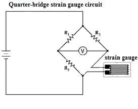
Fig. 21.1 Strain gauge resistance measurement using wheatstone bridge
The strain gauge represents the resistance R4 whose value depends upon the physical variable being measured. Under balanced conditions;
R4 = R2 (R3 / R1)
The ratio of resistors R3 and R1 is fixed for a particular measurement. The bridge is balanced by varying the value of resistor R2. Thus if three resistances are known the fourth may be determined.
21.2 Capacitive Pressure Transducer
The capacitance between two metal plates changes if the distance between these two plates changes. A variable capacitance pressure transducer is as shown in Fig. 21.2. The movable plate in the capacitor is the diaphragm. When the pressure is applied on the diaphragm it deflects and changes its position, due to which the distance between the plates is changed. The change in capacitance between a metal diaphragm and a fixed metal plate is measured and calibrated to the change in pressure. These pressure transducers are generally very stable and linear. They can withstand vibrations. But they are sensitive to high temperatures and are more complicated to setup than most pressure sensors. Their performance is also affected by the dirt and dust as they change the dielectric constant
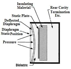
Fig. 21.2 Variable capacitance pressure transducer
21.3 Potentiometric Pressure Sensors
The potentiometric pressure sensor provides a simple method for obtaining an electrical output from a mechanical pressure gauge. The device consists of a precision potentiometer, whose wiper arm is mechanically linked to a Bourdon or bellows element (Fig. 21.3). The movement of the wiper arm across the potentiometer converts the mechanically detected sensor deflection into a resistance measurement, using a Wheatstone bridge circuit.
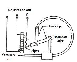
Fig.21.3 Potentiometric pressure sensors
Potentiometric pressure sensors drive a wiper arm on a resistive element. It consists of a potentiometer (a variable resistance) which is made by winding resistance wire around an insulated cylinder. A movable electrical contact, called a wiper slides along the cylinder, touching the wire at on point on each turn. The position of wiper determines the resistance between the end of the wire and the wiper. A potentiometric pressure sensor has a Bourdon tube as the detecting element that moves the wiper. As the wiper moves the change in resistance between the terminals is equivalent to the pressure sensed by the Bourdon tube.
These devices are simple and inexpensive. Resistance can easily be converted into a standard voltage or current signal. They also provide a strong output that can be read without additional amplification. This permits them to be used in low power applications. They are however used in low-performance applications, such as, dashboard oil pressure gauges.
For reliable operation the wiper must bear on the element with some force, which leads to repeatability and hysteresis errors. They have finite resolution, as the wiper moves from one turn to the next the resistance jumps from one value to the other. Errors also will develop due to mechanical wear of the components and of the contacts. Each time the wiper makes and breaks contact with a turn of wire, it causes an extra electrical signal, which is called noise. The addition of noise to the standard electrical signal makes the signal some what confusing. The amount of noise becomes greater as the potentiometer wears out. To reduce the noise some potentiometer are made by depositing a resistance material on a non-conducting ceramic surface. The wiper moves over this surface just as in a wire wound potentiometer, but the resistance can change continuously rather than in increments and is less electrical noise.
21.4 Inductive Pressure Transducer
Reluctance in a magnetic circuit is equivalent to resistance in the electric circuit. Whenever the spacing or coupling between two magnetic devices or coils changes, the reluctance between them also changes. Thus a pressure sensor can be used to change the spacing or coupling between two coils by moving one part of the magnetic circuit. This changes the reluctance between the coils, which in turn changes the voltage induced by one coil in the other. This phenomenon has been explained in the construction and working of LVDT in Lesson 17.
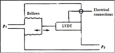
Fig. 21.4 Inductive pressure transducer
LVDTs and other inductive devices are used to convert the displacement motion of bellows or Bourdon tube into proportional electrical signals. Fig. 21.4 shows how an LVDT can be connected to the bellows so that the pressure measurement is converted directly from displacement to voltage. In addition, the displacement and pressure are nearly linearly related, and because the LVDT voltage is linear with displacement, the voltage and pressure are also linearly related.