Module 5. Transducers
Lesson 25
MEASUREMENT OF FLOW
25.1 Introduction
Flow measurement
is the quantification of bulk fluid movement. Flow rate and the quantity is one
of the important process variable requiring frequent measurements. Flow rate
measurement plays an important role in plant material balancing, quality
control and the operation of any continuous process. In engineering contexts,
the volumetric flow rate is usually given the symbol ‘Q’,
and the mass flow rate, the symbol ‘![]() ’. Flow measurements find applications in transportation
of fluids and slurries, gas and water supply systems, irrigation system and
industrial process control. Many accurate and reliable methods are available
for the flow measurements.
’. Flow measurements find applications in transportation
of fluids and slurries, gas and water supply systems, irrigation system and
industrial process control. Many accurate and reliable methods are available
for the flow measurements.
25.2 Orifice and Venturi Flow Meters
Differential pressure flow meters, including the orifice meter, venturi meter, and flow nozzle meter, are widely used to measure pipe flow rate. In each case, a constriction in the flow path causes a pressure drop across the meter. The relationship is derived from Bernoulli’s theorem which states that in a flowing stream, the sum of the pressure head, the velocity head and the elevation head at one point is equal to their sum at another point. The pressure head is the vertical distance through which the liquid would rise in an open end tube as a result of static pressure. The pressure drop across the meter is thus measured and correlated with flow rate. These devices are also called the variable head flow meters. They measure the volume rather than the mass flow rates, the latter however can be computed.
There are several designs of such flow meters, based on the mode of restriction in the flow line, such as, orifice plate or venturi tube. The orifice plates are the simplest and cheapest form of element which is inserted in the line and the pressure drop across it is measured. The Venturi effect is the reduction in fluid pressure that results when a fluid flows through a constricted section of pipe as shown in Fig. 25.1. It consists of a tube with a short, narrow center section and widened, tapered ends, so that a fluid flowing through the center section at a higher velocity than through an end section creates a pressure differential that is a measure of the flow of the fluid.
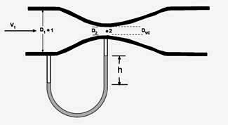
Fig. 25.1 Venturi flow meter
The venturi tube are made up of cast iron or steel and are built in several forms, such as long form, short form and eccentric form etc. they are available in sizes from 100 mm to 800 mm.
25.3 Rotameter
The term rotameter derives from early versions of the floats, which had slots to help stabilize and center them and which caused them to rotate. The operating principle of rotameter is based on a float of given density's establishing an equilibrium position where, with a given flow rate, the upward force of the flowing fluid equals the downward force of gravity. It is achieved by rising in the tapered tube with an increase in flow until the increased annular area around it creates a new equilibrium position. By design, the rotameter operates in accordance with formula for all variable-area meters, directly relating flow rate to area for flow. Rotameters are the most widely used type of variable-area flow meter. When the flow is constant, the float stays in one position that can be related to the volumetric flow rate. That position is indicated on a graduated scale. Note that to keep the full force of gravity in effect, this dynamic balancing act requires a vertical measuring tube.
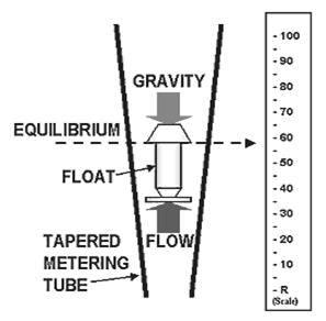
Fig. 25.2 Rotameter
The gradually increasing diameter of the tapered tube provides an increase in the annular area around the float. The volumetric flow rate is given by the following equation:
Q = kA (gh)1/2
where:
Q = volumetric flow rate, litres per hr.
K = constant
A = annular area between the float and the tube wall
g = acceleration due to gravity
h = pressure drop (head) across the float
With ‘h’ being constant in a variable area meter, we have area ‘A’ as a direct function of flow rate ‘Q’. Thus, the taper of the rotameter tube can be designed so that the height of the float in the tube is a measure of flow rate.
The two basic components of every rotameter as shown in Fig. 25.2 are the tapered metering tube and the float. Tube sizes vary from 1/16 to 4 inch. Arbitrary linear scale graduations can be put for display of 0%–100%. The scale calibration can be made in terms of direct reading of a specific gas or liquid for flow rates of the fluid being measured. The metal body of the rotameter is rigidly constructed to maintain tube alignment. The end fittings provide process pipe connections, either threaded female or flanged with O-rings or packing glands for sealing at both ends of the tube. Provisions are also made for easy removal of the glass tube for cleaning.
In Glass Tube rotameters, the tapered metering tube made of borosilicate glass. The Metal Tube rotameters are designed for applications where the temperature or pressure exceeds the limits of glass tubes. Flow rate is indicated by a pointer on an indicating scale by means of a magnet inside the float, magnetically linked to the pointer. Metal tube meters are generally made of corrosion-resistant type 316 stainless steel. They are well suited to measuring steam flow where conditions or regulations prevent the use of glass, and useful as well where the nature of the fluid would preclude reading a float position. Plastic tube rotameters are the cost-effective alternative to glass or metal meters for a wide variety of fluid measurements. In this tube is made up of a single piece of clear acrylic that is practically unbreakable in most industrial process applications. Floats are available in a variety of shapes and materials, with varying densities that can be used to change the meter's range and to resist corrosion from the measured fluid. The float materials include Type 316 stainless steel, tantalum, Monel, Teflon, and PVC.
To select the correct rotameter for a given application, it is important to have the data with regard to the nature of the fluid, the fluid density and viscosity at the specified operating temperature, operating and maximum temperature and pressure and the minimum and maximum flow rates.
25.4 Ultrasonic Flow Meters
The ultrasonic flow meters use transducers to transmit and/or receive ultrasonic waves in the process of pipe flow measurement. The ultrasonic waves have the frequency > 20 kHz. Two types of ultrasonic flow meter are in common use to measure pipe flow rate. They are the doppler ultrasonic flow meter and the transit time ultrasonic flow meter.
i) Doppler ultrasonic flow meter
In a doppler ultrasonic flow meter, as shown in Fig. 25.3 (a), one transducer transmits ultrasonic waves and the other transducer receives ultrasonic waves. The fluid for which pipe flow rate is being measured must have material like particles or entrained air that will reflect ultrasonic waves. The frequency of the transmitted beam of ultrasonic waves will be altered, or shifted, due to being reflected by the air bubbles or particles. The frequency shift, which is proportional to the fluid flow rate through the meter, is measured by the receiving transducer. The receiving transducer can thus generate a signal that is proportional to flow rate.
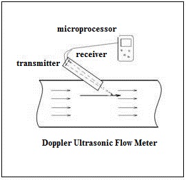
Fig. 25.3 (a) Doppler ultrasonic flow meter
ii)
Transit time
ultrasonic flow meter
This type of meter measures the difference in travel time for pulses transmitted against the flow and pulses transmitted in the direction of the flow rate. In the transit time ultrasonic flow meter shown in Fig. 25.3 (b), both transducers serve as transmitter and receiver of ultrasonic waves alternately.
The two transducers are mounted on the outside of the pipe so that one is a known distance upstream of the other. A pulse will be transmitted by the downstream transducer, for example, and it will be detected by the upstream transducer, giving the 'transit time' for upstream flow. Then the process will be reversed and the upstream transducer will transmit a pulse to be detected by the downstream transducer, to give a 'transit time' in the direction of flow. A microprocessor is typically used to calculate the pipe flow rate based on the difference between the downstream transit time and the upstream transit time.

Fig. 25.3 (b) Transit time ultrasonic flow meter
The doppler and transit time ultrasonic flow meter both cause negligible pressure drop when in use for pipe flow measurement. The effect of fluid viscosity on pipe flow rate measurement is negligible for both types. The doppler ultrasonic flow meter can be used to measure the pipe flow rate of dirty liquids and slurries. A transit time ultrasonic flow meter can be used for pipe flow measurement of both liquids and gases. Both the doppler and transit time ultrasonic flow meter have a cost that is relatively high in comparison with other types of pipe flow meter.
25.5 Turbine Flow Meter
The turbine flow meter (Fig. 25.4) translates the mechanical action of the turbine rotating in the liquid flow around an axis into a user-readable rate of flow in litres per min. The turbine tends to have all the flow traveling around it. The turbine wheel is set in the path of a fluid stream. The flowing fluid impinges on the turbine blades, imparting a force to the blade surface and setting the rotor in motion. When a steady rotation speed has been reached, the speed is proportional to fluid velocity.
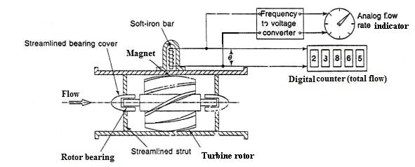
Fig. 25.4 Turbine flow meter
Turbine flow meters are used to measure total quantity of flow. They can also be used for the measurement of natural gas and liquid flow. The flow direction is generally straight through the meter, allowing for higher flow rates and less pressure loss than displacement-type meters. Strainers are generally required to be installed in front of the meter to protect the measuring element from gravel or other debris that could enter the water distribution system. Turbine meter bodies are commonly made of bronze, cast Iron, or ductile iron. Internal turbine elements can be plastic or non-corrosive metal alloys.
25.6 Target Flow Meter
The drag force on a body (target plate) becomes the measure of the flow rate. The drag force on the target plate can be measured by attaching a suitable force measuring transducer. Cantilever beam arrangement with bonded strain gauges is commonly used to measure the drag force developed on the target plate.
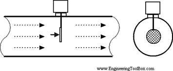
Fig. 25.5 Target flow meter
Target Flow Meter can be used for any type of liquid,
gas, steam or cryogenics. There are no moving parts such as bearings etc. to
wear out causing failures. It can be used for any size of line from 12mm and
up, with any type of mounting. It can accept bi-directional flow, where signal
polarity indicates direction of flow. The calibration of target flow meter,
however, must be verified in the field.
25.7 Rotary Vane Flow Meter
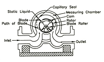
Fig. 25.6 Rotary vane flow meter
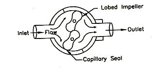
Fig. 25.7 lobe type flow meter
25.8 Electro Magnetic Flow Meter
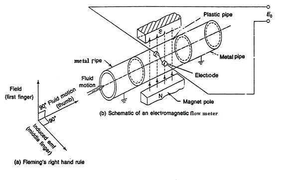
Fig. 25.8 Electromagnetic flow meter