Module 5. Transducers
Lesson 26
MEASUREMENT OF SPEED AND HUMIDITY
26.1 Introduction
Speed is a rate variable defined as a time-rate of motion. Common form and units of speed measurement include: linear speed expressed as m/s or km/h and angular speed of a rotating component usually expressed as revolution per minute or rad/s. Measurement of rotational speed has acquired prominence over the linear speed. Continuous measurement of linear speed is usually made in terms of angular speed and then converted in to linear speed of a reciprocating part. RPM measurement is important when controlling or monitoring the speed of motors, conveyors, turbines, etc.
Several methods for the measurement of rotational speed are available. Angular measurements are made with a device called tachometer. The word "tachometer" is derived from the Greek words tachos, meaning "speed," and metron, meaning "to measure." Tachometer may be broadly classified in to two categories: mechanical tachometer and electrical tachometer.
26.2 Mechanical Tachometer
Mechanical tachometer employs only mechanical parts and mechanical movements for the measurement of speed. Most common type of mechanical tachometers are hand tachometer and the revolution counter.
26.2.1 Hand-held tachometer
The hand-held tachometer is shown in Fig. 26.1. It consists of a worm gear attached to spindle. The worm gear meshes with a spur gear that in turn moves a pointer on calibrated dial to indicate revolutions. Generally two dials are placed in position. In one dial each division represents one revolution of the spindle while on the other on division represents the one revolution of the former. A stop watch is attached to the revolution. For measuring the speed the tachometer is manually pressed at the contact point at the rotating shaft whose speed is to be measured. The spindle starts rotating and provides motion to the pointer through the worm gear indicating the total revolution of the shaft in a given period of time noted with the help of a stop watch. The average speed is then calculated.
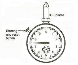
Fig.26.1 Hand-held tachometer
In another arrangement an automatic timer is used to indicate the speed directly in rpm on the calibrated dial. The spindle operates when brought in contact with the shaft. The counter however does not function until the start button pressed to start the watch and engage the automatic clutch. Depressing the starting knob also serves to wind the timer watch. The revolution counter automatically gets disengaged after a short period of time. These tachometers can measure up to a speed of 30000 rpm with an accuracy of 1%. The revolution counter is used with a timing device to determine the number of revolutions in a measured length of time. Thus it measures an average rotational speed over a short interval of time rather than instantaneous rotational speed.
Digital tachometers have become more common as they give numerical readings instead of using dials and needles.
26.2.2 Centrifugal tachometer
The principle of operation of centrifugal tachometer is that the centrifugal force is proportional to the speed of rotation. The schematic diagram of a centrifugal tachometer is shown in Fig. 26.2. Two small weights in the form of balls are attached to the spindle and rotate along with the spindle. As the spindle rotates the centrifugal force is developed by these balls. This centrifugal force compresses the spring and a grooved collar or sleeve attached to its free end slides on the spindle and its position can be calibrated with the spindle speed. Through a series of linkages, motion of the sleeve is amplified and communicated to the pointer of the instrument to indicate speed. Certain attachments are provided with the spindle to indicate the linear speed. These types of instrument can be used up to 40000 rpm. They are also used in the speed governors to break circuit for speed control. These tachometers have a distinct advantage over revolution counter in that they indicate whether or not the speed remains substantially constant.
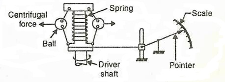
Fig. 26.2 Centrifugal tachometer
26.3 Electrical Tachometer
Electrical tachometers provide the advantages of electrical transducers and in view of this they are preferred over mechanical tachometer. They depend for its indication upon an electrical signal generated in proportion to the rotational speed of the shaft. Depending upon the type of transducer, electrical tachometers have been constructed in the variety of designs. For example commutated capacitor tachometer based on alternately charging and discharging capacitor controlled by speed of rotating member. In eddy current type tachometer the rotating shaft rotates a permanent magnet and this induces eddy currents in a disc. The eddy current produces a torque that rotates the disc against the torque of a spring. The disc turns in the direction of rotating magnetic field until the torque developed equals that of spring. A pointer attached to the disc indicated the rotational speed on a calibrated scale. The tachometer generator has been developed on the principle that the e.m.f. generated depends upon the magnetic field and the speed. If for the field the permanent magnetic pole pieces are used then the generated voltage only depends upon the speed. The tachogenerator may be AC or DC type of tachometer depending upon the taking out means of e.m.f. generated. Hence the speed can be calculated by measuring the e.m.f. generated.
26.4 Photoelectric Tachometer
The photoelectric tachometer utilizes a rotating shaft to intercept a beam of light falling on a photo conductive cell. The shaft has an intermittent reflecting (white) and non reflecting (black) surfaces. When a beam of light hits the reflecting surface on the rotating shaft, light pulses are obtained and the reflected light is focused on to the photoelectric cell. The frequency of light pulses is proportional to the shaft speed and so will be the frequency of electric output pulses from the photo electric cell.
Another similar method consists of an opaque disc mounted on the rotating shaft as shown in Fig. 26.3. The disc has a number of evenly spaced peripheral holes. A light source is placed on one side of the disc and a light sensor on the other side of the disc inline with it.
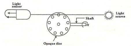
Fig. 26.3 Photoelectric tachometer
When the opaque portion is between the light source and the light sensor, no light falls on the light sensor and there is no output. At the time when a hole appears between the two, the light illuminates the sensor and a pulse of voltage is produced. The frequency of pulse generation is determined by the number of holes in the disc and its speed of rotation. Since the number of holes is fixed in the disc the frequency of the output is calibrated to measure the rotational speed of the rotating shaft. Photoelectric tachometer is a digital instrument. It however requires replacing the light source periodically.
26.5 Measurement of Humidity
Humidity is due to the presence of water vapours in a gas or air. It is generally measured in terms of absolute humidity, relative humidity or the dew point temperature. The absolute humidity is the mass of water vapour present in the unit mass of the moist air or gas. The relative humidity is the ratio of the water vapour pressure of the in a mixture of gas to the water vapour pressure in a saturated mixture the same temperature. The dew point temperature is the saturation temperature of the gas water mixture. At dew point the relative humidity is 100%.
The instrument which measures the humidity directly is known as hygrometer. It can be calibrated to indicate the absolute or relative humidity. The most common humidity measuring instrument is the sling psychrometer which has two thermometers. The dry bulb thermometer measures the ambient temperature where as the wet bulb thermometer measures the temperature of saturated air i.e. the reduction in temperature due to evaporative cooling. The relative humidity is determined from the two temperatures readings with the help of psychrometric chart.
The other most frequently used hygrometers are the resistive hygrometer, impedance type hygrometer and the dew point recorder.
26.6 Resistive Hygrometer
A typical resistive type hygrometer is shown in Fig. 26.4. It consists of two metal wire grids which are bonded to a plastic sheet. Over this whole there is a coating of moisture sensitive chemical lithium chloride, which exhibits a change in resistivity with the humidity.
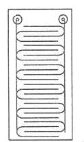
Fig. 26.4 Resistive hygrometer
If the sensing unit is exposed to variation in humidity, then there is a change in resistance. At higher relative humidity the lithium chloride absorbs more moisture and the resistance decreases. The resistance of the sensing unit is measure by applying AC to the Wheatstone bridge. The DC voltage is not applied as it tends to break down the lithium chloride.
26.7 Impedance Type Hygrometer
It measures the moisture content of the sample by means of a probe whose impedance is a function of the vapours present in the air or gas. A typical impedance type probe is shown in Fig. 26.5. The probe consists of an aluminum strip, which is anodized to form porous layer of aluminum oxide. A thin coat of gold is applied over the aluminum oxide. Leads from the gold and aluminum electrodes connect the sensing element to the external circuitry. Water vapours penetrate the gold layer and equilibrate over the aluminum oxide. The number of water molecules absorbed over the aluminum oxide is a function of water vapour present in the sample. This contributes towards an increase in the conductivity of the aluminum oxide. The total probe impedance is the reciprocal of the probe conductivity.
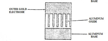
Fig. 26.5 Impedance type hygrometer
26.8 Dew Point Recorder
This method uses a resistive hygrometer. As shown in Fig. 26.6, it consists of a thin metal tube covered with a glass cloth saturated with lithium chloride. A double winding of silver is made over the glass cloth. The winding is connected to AC supply. The salt picks up moisture from the surrounding and electric conductivity between the wire changes. At low humidities the current flow through winding is small and the temperature rise of the winding is low. Conversely at high moisture the current flow though the winding is large and the temperature of the coil is high. The inside temperature of the cell is measured with the help of thermometer and the absolute humidity or the dew point temperature is determined. The instrument has a fast response and can be used to measure the dew point with an accuracy of ±2%.
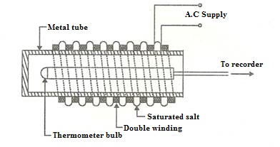
Fig. 26.6 Dew point recorder
26.9 Hair Hygrometer
Hair and other organic materials absorb moisture from the ambient atmosphere. The amount depends upon the temperature and the partial pressure of atmosphere. As the water content of the hair increases, the hair lengthens, closely approximating the relative humidity. Hairs are joined in parallel to form a hygrometer probe. They are sufficiently apart to give the free access to moisture. Hairs are in firm tension to maintain them straight. Animal or human hairs and synthetic fibers are used to form such probes. The lower and the upper limits for the use of hair hygrometer are 15 to 95% relative humidity.