Module 6. Process control
Lesson 28
CONTROL SYSTEM PARAMETERS
28.1 Introduction
A control system monitors and determines a difference between a desired and measured parameter values, applies a weighting factor to the difference and selects a control strategy based on the weighted difference. The weighting factor generally reflects the confidence in the accuracy of the parameter value determined by the parameter monitor. The weighting factor may be determined based on one or more ambient operating conditions or parameters, or on statistical analyses of monitor values and/or control system parameter values.
28.2 Control System Parameters
28.2.1 Error
Error is the difference between the measured variable and the setpoint. Error can be either positive or negative. The objective of any control scheme is to minimize or eliminate error. The deviation or error of dynamic variable from set point is given by:
E = Cm - Csp
Where E = error
Cm = measured value of variable
Csp = set point of variable
The above equation expresses error in an absolute sense, usually in units of measured analog of control signal. Note that a positive error indicates a measurement above the set points whereas a negative error indicates a measurement below the set point.
28.2.2 Variable range
The dynamic variable under control or controlled variable has a range of values within which control is required to be maintained at set point. This range can be expressed as the minimum and maximum values of the dynamic variable or the nominal value plus and minus the spread about this nominal value e.g. if a standard signal 4-20 mA transmission is employed, then 4 mA represents the minimum value of the variable and 20 mA the maximum value.
28.2.3 Control parameter (output) range
It is the possible range of values of final control element. The controller output is expressed as a percentage where minimum controller output is 0% and maximum controller is 100%. But 0% controller output does not mean zero output. For example, it is necessary requirement of the system that a steam flow corresponds to 1/4th opening of valve. The controller parameter output has a percentage of full scale when the output changes within the specified limits in expressed as:
P = [Sp – Smin]/ [Smax – Smin] x 100
Where:
P = Controller output as percentage of full scale
Sp = Value of the output
Smax = Maximum value of the controlling parameter
Smin = Minimum value of the controlling parameter
28.2.4 Control lag
Processes have the characteristic of delaying and retarding changes in the values of the process variables. This characteristic greatly increases the difficulty of control. The control system can have a lag associated with it. The control lag is the time required by the process and controller loop to make the necessary changes to obtain the output at its set point. The control lag must be compared with process lag while designing the controllers. A process time lag is the general term that describes the process delays and retardations. It refers to the time for the process control loop to make necessary adjustments to the final control element e.g. if a sudden change in liquid temperature occurs, it requires some finite time for the control system to physically actuate the steam control valve.
28.2.5 Dead time
Sometimes a dead zone is associated with the process control loop. The time corresponding to dead zone is called dead time. This is the elapsed time between the instant a deviation (error) occurs and when the corrective action first occurs.
28.3 Controller Modes
The method used by the controller to correct the error is the control mode. Controller modes are an expression of relation between controller output and dynamic variable deviation from the set point. The actions of controllers can be divided into groups based upon the functions of their control mechanism. Each type of controller has advantages and disadvantages and meets the needs of different applications. Grouped by control mechanism function, the two types of controllers are:
1. Discontinuous controllers
2. Continuous controllers
28.3.1 Continuous controller mode
In this mode there is a possibility of smooth variation in control parameter and the controllers automatically compare the value of the process variable to the set-point to determine if an error exists. If there is an error, the controller adjusts its output according to the parameters that have been set in the controller. When there is an error, the controller makes a change in its output. It determines:
· How much? Proportional Mode
· How long? Integral Mode
· How fast? Derivative Mode
28.3.2 Discontinuous controller mode
In this mode controller command initiates a discontinuous change in control parameter. The manipulated variable of a discontinuous controller mode can only be changed in set steps. The best-known discontinuous-action controller is the two-step control that can only assume the conditions ‘on’ or ‘off’. An example is the thermostat of a hot air oven. It switches the electric current for the heating element ‘on’ or ‘off’ depending on the set temperature.
28.3.3 Types of discontinuous controller modes
The choice of operating modes for any given process control system is a complicated decision. It involves not only process characteristics but cost analysis, product rate, and other industrial factors. The different types of discontinuous controller operating modes are defined as follows:
(A) Two Position Controller Mode: A two position controller mode uses a device that has two operating conditions: completely on or completely off. These also called ON-OFF control or Discrete controllers. On /off control activates an output until the measured value reaches the reference value. Fig. 28.1 shows the input to output characteristic for a two position controller for a refrigerator that switches from its ‘OFF’ to its ‘ON’ state when the measured variable increases above the set point.
Conversely, it switches from its ‘ON’ state to its ‘OFF’ state when the measured variable decreases below the set point. This device provides an output determined by whether the error signal is above or below the set point. The magnitude of the error signal is above or below the set point. The magnitude of the error signal past that point is of no concern to the controller.
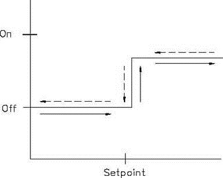
Fig. 28.1 Two position controller input/output relationship
While simple and low cost, this mode of control has a tendency to overshoot the desired value. Flow Diversion Valve (FDV) used in HTST plant and solenoid valves are two position ON-OFF controller.
(B) Multi-position Mode or Multistep Mode Controllers
Multistep controllers are controllers that have at least one other possible position in addition to on and off. Multistep controllers operate similarly to discrete controllers, but as set-point is approached, the multistep controller takes intermediate steps. Therefore, the oscillation around set-point can be less dramatic when multistep controllers are employed than when discrete controllers are used. This mode is used to provide several intermediate values rather than only two settings of controller output. This discontinuous control mode is used to reduce the cycling behaviour and also overshoot and undershoot inherent in two position control. This mode is represented by:
P = Pi Ep > Ei I = 1, 2, 3,………………………….n
The meaning here is that as error exceeds certain set limits + Ei, the controller output is adjusted to preset values Pi.
(C) Floating Control Modes
In this control mode, specific output of the controller is not uniquely determined by error. If error is zero, the output will not change but remains (floats) at whatever settings it was when the error went to zero. When the error moves off zero, the controller output begins to change e.g. a floating control will operate a control valve which, as level rises and falls will throttle down or gradually open a level control valve in the inlet (or outlet) line, thereby controlling the level at a pre-set height in the tank.