Module 6. Process control
Lesson 30
FINAL CONTROL ELEMENTS AND ACTUATORS
30.1 Introduction
Final control elements are devices that complete the control loop. They link the output of the controlling elements with their processes. Some final control elements are designed for specific applications. The final control element is the last element of the closed control loop that implements the control action. It receives the output signal (control or actuating signal) from a process controller and adjusts accordingly the value of the manipulated variable by changing the amount of matter or energy entering the process in a way to bring the controlled variable (process variable) to its set point. The final control element is probably the most important because it exerts a direct influence on the process.
For example, neutron-absorbing control rods of a reactor are specifically designed to regulate neutron-power level. However, the majority of final control elements are general application devices such as valves, dampers, pumps, and electric heaters. Valves and dampers have similar functions. Valves regulate flow rate of a liquid while dampers regulate flow of air and gases. Pumps, like valves, can be used to control flow of a fluid. Heaters are used to control temperature.
These devices can be arranged to provide a type of "on-off" control to maintain a variable between maximum and minimum values. This is accomplished by opening and shutting valves or dampers or energizing and de-energizing pumps or heaters. On the other hand, these devices can be modulated over a given operating band to provide a proportional control. This is accomplished by positioning valves or dampers, varying the speed of a pump, or regulating the current through electric heater. There are many options to a process control. Out of the final control elements discussed, the most widely used in power plants are valves. Valves can be easily adapted to control liquid level in a tank, temperature of a heat exchanger, or flow rate. Control valves are the single most common type of final control element in process.
30.2 Control Valves
A control valve is a valve with a pneumatic, hydraulic, electric or other externally powered actuator that automatically, fully or partially opens or closes the valve to a position dictated by signals transmitted from controlling instruments.
Control valves are used primarily to throttle energy in a fluid system and not only for shut-off purposes. Their internals must withstand high fluid velocity and turbulence for long periods without maintenance. A control valve is simply a variable orifice that is used to regulate the flow of a process fluid according to the requirements of the process.
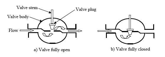
Fig. 30.1 Typical globe type control valve
Fig. 30.1 illustrates a typical globe-type control valve body in both the fully open and fully closed positions. In a control valve, an actuator that is connected to the valve’s plug stem moves the valve between the open and closed positions to regulate flow in the process. The valve body is mounted in the process fluid line and is used to control the flow of fluid in the process. The body of a control valve is generally defined as the part of the valve that comprises the main boundary, including the connecting ends. Valves are classified into two general types based on the movement of the valve’s closure part: linear and rotary.
30.3 Types of Actuator
An actuator is the part of a final control device that causes a physical change in the final control device when signaled to do so. The most common example of an actuator is a valve actuator, which opens or closes a valve in response to control signals from a controller. By themselves, valves cannot control a process. Manual valves require an operator to position them to control a process variable. Valves that must be operated remotely and automatically require special devices to move them. These devices are called actuators. Actuators are often powered pneumatically, hydraulically, or electrically. Diaphragms, bellows, springs, gears, hydraulic pilot valves, pistons, or electric motors are often parts of an actuator system. There are four principal types of actuator:
· Pneumatic
· Hydraulic
· Solenoid
· Electric Motor
30.3.1 Pneumatic actuator with valve
The pneumatic valve is an air-operated device which controls the flow through an orifice by positioning appropriately a plug (Fig. 30.2 and 30.3).

Fig. 30.2 Air-to-close pneumatic actuator with valve
The plug (1) is placed in the orifice (2) of the valve and attached to the end of the stem (3). The orifice is placed inside the body of the valve (4) made of cast iron, alloy steels, alloy steels plus corrosion-resistant alloys, or bronze. The upper part of the final control element is an actuator (5). A diaphragm (6) divides this actuator in two chambers. The upper end of the stem is supported on the diaphragm. When the airs pressure (the output signal from a pneumatic controller) above the diaphragm increases, the diaphragm deflects and the stem moves downwards thus restricting by the plug flow of the fluid through the orifice. This type of a pneumatic valve is called ‘air-to-close’ valve.
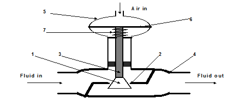
Fig. 30.3 Air-to-open pneumatic actuator with valve
When the air pressure goes down the stem under the action of a spring (7) will move upwards, thus opening the orifice. There is another type of valves, which operate in opposite action, i.e., when the air pressure increases the plug opens the orifice. Such valves are called ‘air-to-open’ valves. If the air pressure varies from 20 to 100 kPa the plug is moved from a fully open to fully closed position.
30.3.2 Hydraulic actuators
Pneumatic actuators are normally used to control processes requiring quick and accurate response, as they do not require a large amount of motive force. However, when a large amount of force is required to operate a valve (for example, the main steam-stop valves), hydraulic actuators are normally used. Hydraulic actuators use fluid displacement to move a piston in a cylinder positioning the valve as needed for 0-100% fluid flow. Although hydraulic actuators come in many designs, piston types are most common.
A typical piston-type Hydraulic Actuator is shown in Fig. 30.4.
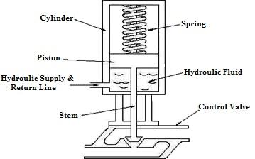
Fig. 30.4 Piston-type hydraulic actuator
It consists of a cylinder, piston, spring, hydraulic supply and returns line, and stem. The piston slides vertically inside the cylinder and separates the cylinder into two chambers. The upper chamber contains the spring and the lower chamber contains hydraulic oil. The hydraulic supply and return line are connected to the lower chamber and allows hydraulic fluid to flow to and from the lower chamber of the actuator. The stem transmits the motion of the piston to a valve.
When the hydraulic force is greater than the spring force, the piston begins to move upward, the spring compresses, and the valve begins to open. As the hydraulic pressure increases, the valve continues to open. Conversely, as hydraulic oil is drained from the cylinder, the hydraulic force becomes less than the spring force, the piston moves downward, and the valve closes. By regulating amount of oil supplied or drained from the actuator, the valve can be positioned between fully open and fully closed.
30.3.3
Electric solenoid actuators
Solenoid actuators are used on small valves and employ an electromagnet to move the stem which allows the valve to either be fully open or fully closed. A typical electric solenoid actuator is shown in Fig. 30.5. It consists of a coil, armature, spring, and stem.
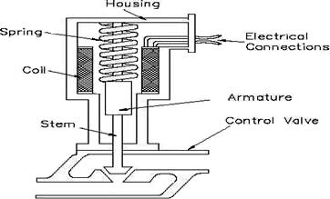
Fig. 30.5 Electric solenoid actuator
The coil is connected to an external current supply. The spring rests on the armature to force it downward. The armature moves vertically inside the coil and transmits its motion through the stem to the valve.
When current flows through the coil, a magnetic field forms around the coil. The magnetic field attracts the armature toward the center of the coil. As the armature moves upward, the spring collapses and the valve opens. When the circuit is opened and current stops flowing to the coil, the magnetic field collapses. This allows the spring to expand and shut the valve.
A major advantage of solenoid actuators is their quick operation. Also, they are much easier to install than pneumatic or hydraulic actuators. However, solenoid actuators have two disadvantages. First, they have only two positions: fully open and fully closed. Second, they don’t produce much force, so they usually only operate relatively small valves.
30.3.4
Electric motor actuators
An electric motor is composed of a rotating center, called the rotor and a stationary outside, and called the stator. These motors use the attraction and repulsion of magnetic fields to induce forces, and hence motion. Equipped with limit switches and/or torque limiters, the electric motor actuator has the capability of 0-100% control and has not only a motor but also a manual hand wheel, and a clutch and gearbox assembly.
Typical electric motors use at least one electromagnetic coil, and sometimes permanent magnets to set up opposing fields. When a voltage is applied to these coils the result is a torque and rotation of an output shaft. There is a variety of motor configuration the yields motors suitable for different applications. Most notably, as the voltages supplied to the motors will vary the speeds and torques that they will provide.
Electric motor actuators vary widely in their design and applications. Some electric motor actuators are designed to operate in only two positions (fully open or fully closed). Other electric motors can be positioned between the two positions. A typical electric motor actuator is shown in Fig. 30.6. Its major parts include an electric motor, clutch and gear box assembly, manual hand wheel, and stem connected to a valve.
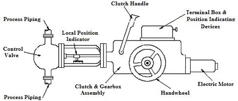
Fig. 30.6 Electric motor actuator
The motor moves the stem through the gear assembly. The motor reverses its rotation to either open or close the valve. The clutch and clutch lever disconnects the electric motor from the gear assembly and allows the valve to be operated manually with the hand wheel.
Most electric motor actuators are equipped with limit switches, torque limiters, or both. Limit switches de-energize the electric motor when the valve has reached a specific position. Torque limiters de-energize the electric motor when the amount of turning force has reached a specified value. The turning force normally is greatest when the valve reaches the fully open or fully closed position. This feature can also prevent damage to the actuator or valve if the valve binds in an intermediate position.