Module 6. Process control
Lesson 31
INSTRUMENTATION AND CONTROLS IN DAIRY PLANT
31.1 Electromagnetic Switching Relay
Electromagnetic switching relay is based on the principle of electromagnetic induction and is used to switch on the power supply to electric equipments. It is employed to supply 24 V D.C. supply to Solenoid Valves, 220 to 440 V for motor starters or any other electrical equipment. The working switching relay is shown in the Figure 31.1.
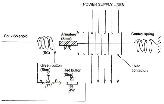
Fig. 31.1 Electromagnetic switching relay
When the green button (marked Start) is pressed the electric circuit provides the supply to the Solenoid Coil (SC). The coil becomes an electromagnet and attracts the steel Armature to the left. This movement of armature makes the contact of movable contactors to the fixed contactors and completes the circuit through the ends A and B, thus giving the power supply to any equipment connected to the terminals at the end B. The start button opens up when our finger is removed from the button. But the current to coil is maintained through auxiliary contacts A&B, which is connected in parallel to the Green button switch as shown in the figure. By closing the Red button the circuit to the coil breaks and the control spring pulls the movable contactors to the right, thus cutting the power supply and the equipment stops.
31.2 Air Operated Milk Valve
A solenoid valve is an electro-mechanically operated valve. The valve is controlled by an electric current through a solenoid. It has two main parts: the solenoid and the valve. The solenoid converts electrical energy into mechanical energy which, in turn, opens or closes the valve mechanically. One such air operated milk valve used in dairy plants is shown in figure 3.2.
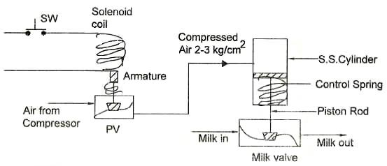
Fig. 31.2 Air operated milk valve
In the above figure the SW is the switch, it could be a manual start switch or a switch operated by any of the equipment used for the controlling parameters like, pressure, temperature, flow etc. By closing the switch SW power is supplied to the solenoid through SW. A pilot valve PV is attached to the armature of the solenoid. When the SW is closed the movement of the armature opens the pilot valve and the compressed air enters the SS Cylinder. The compressed air at the pressure of 2-3 kg/cm2 moves the piston down and closes the milk valve. The reverse happens when the SW is disconnected. The air supply to the cylinder is closed and the air is exhausted from the cylinder (not shown in the figure). Now the movement of the valve is carried out by the control spring and the milk valve is opened.
31.3 Self Acting Steam Thermostat
Figure 3.3 shows a self acting steam thermostat with glycerin liquid, commonly used in dairy plants. A SS sensing bulb filled with glycerin under pressure is immersed in the tank, the contents of which are heated by steam. As the temperature increases the glycerin liquid expands in proportion to the temperature at the sensing bulb. This pushes the piston in the valve and the steam supply is regulated by the steam valve. The glycerin is used because its volumetric expansion is quite high and enough to generate power to operate the steam valve.
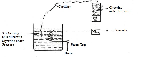
Fig. 31.3. Self acting steam thermostat with glycerin liquid
31.4 Online Denity Transducer
The online density transducer, as shown in figure 3.4, is used in the computerized dairy plants for sensing density, total solids, fat, temperature etc. The density measurement is based on measuring the period of oscillation of a mechanical oscillator operated at its normal frequency.
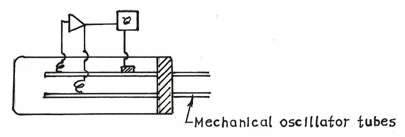
Fig. 31.4. Online density transducer
The oscillator consists of two straight parallel tubes, which are flown through by the sample. The period of oscillation depends upon the density of the sample within the mechanical oscillator and the mechanical properties of the, like inner diameter, wall thickness, elasticity etc. of the applied tube. Both density and mechanical properties of the tube depend on the temperature of the sample. Thus temperature is also measured and transmitted. The signal processor computes the density, temperature etc. and extrapolates information of total solids, dry weight, fat percent etc. in the sample.
31.5 Temperature Controller Recorders In Htst Pasteuizer
31.5.1 Flow diversion valve controller in HTST pasteurizer
In HTST pasteurizer the raw milk / product is pumped from a constant level tank to the heating section where the temperature is raised to exceed the pasteurization lower limit. The hot product temperature is measured and recorded at the end of the holding tube. If the temperature is less than the pasteurization temperature, the product is sent back to the constant level tank by the flow diversion valve and is recycled. Once the temperature exceeds the pasteurization temperature the flow diversion valve routs the product to the forward flow to the regenerator and cooling sections of the heat exchanger. The operation of a flow diversion controller of an HTST pasteurizer is shown in figure 31.5.
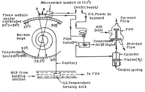
Fig. 31.5 Flow diversion valve controller in HTST pasteurizer
A SS temperature sensing bulb is inserted in the milk line that senses the temperature and provides proportionate signal to the Bourdon element by expansion of liquid through a capillary. The position of the contact ‘A’ attached to the Bourdon element is guided by the movement of the free end of the Bourdon element. As soon as the temperature of milk exceeds 72.5oC the contacts A-B closes. This switches on the micro-switch (MS) that provides the 24 V DC supply to the solenoid operated pilot valve (PV). When the pilot valve opens compressed air enters the cylinder pushes the piston P2 downwards. The stem of the flow diversion valve then moves to the downward position and closes the diverted flow port. Milk thus enters the forward flow line. The reverse happens when the temperature of milk is less than 72.5oC, resulting in the diverted flow.
31.5.2 Control system in HTST pasteurizer
Complete control system of a HTST pasteurization plant is given in figure 31.6 showing the flow recorder controller and the temperature recorder controller. The temperature recorder controller gets the input with regards to the temperatures of hot water, temperature of milk at the end of the holding tube and the temperature of pasteurized chilled milk. Hot water is normally used to heat the milk in a plate heat exchanger. Steam is introduced to the water tank, and the temperature of hot water is normally kept 2 to 3oC above the pasteurization temperature. The temperature of hot water is sensed and sent to temperature controller. Heating will continue until the preset temperature vale is reached.
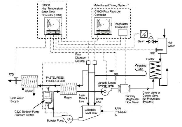
Fig. 31.6 Control system in HTST pasteurizer
31.6 Outlet Air Temperature Controller in Spray Dryer
The outlet air temperature in a spray drying chamber is controlled by keeping the inlet air temperature at a constant level and varying the milk input. The schematic diagram of outlet air temperature control in the spray dryer is given in Fig. 31.7
. 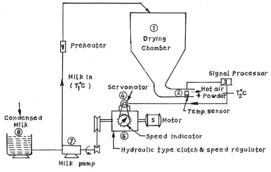
Fig. 31.7 Outlet air temperature controller in spray dryer
A thermistor sensing device senses the air temperature at the outlet of drying chamber at point (2). A Wheatstone bridge circuit is used to compare the measured temperature with the desired temperature. The output of the signal processor at (3) operates the servomotor (4), which rotates in either direction depending upon the outlet air temperature, whether it is more or less than the desired value. The servomotor controls the pressure of oil between the set of clutch plates through a pressure reducing valve. This controls the speed of milk pump and hence the milk input to the dryer to maintain a constant temperature at the outlet.