Module 2. A.C. series and parallel circuits
Lesson 7
CONCEPT OF RESONANCE
7.1 Introduction
An RLC circuit (or LCR circuit) is an electrical circuit consisting of a resistor, an inductor, and a capacitor, connected in series or in parallel. The RLC part of the name is due to those letters being the usual electrical symbols for resistance, inductance and capacitance respectively. The circuit forms a harmonic oscillator for current and will resonate at resonant frequency.
7.2 Concept of Resonance in Series Circuit
The resonance frequency is defined as the frequency at which the impedance of the circuit is at a minimum. Equivalently, it can be defined as the frequency at which the impedance is purely real (that is, purely resistive). This occurs because the impedance (reactance) of the inductor and capacitor at resonance are equal but of opposite sign and cancel out. Thus in a R-L-C series circuit, when the value of the inductance is equal to the capacitance i.e. XL = XC, the circuit is said to be in resonance. For a circuit the value of XL and XC is given as follows:
XL = 2pfL
Where
f = frequency
L = Inductance Units Henry
![]()
where
f = frequency
C = Capacitance unit Farad
At resonant frequency (fr) XL = XC
i.e.,
![]()
![]()
7.2.1 Resonance curve
Resonance curve is plotted between current and frequency. For R-L-C series circuit current approaches maximum value at the resonant frequency (fr) and declines abruptly on either side at that point. It is so due to following reason (Table 7.1):
Table 7.1 Variation in current with frequency
|
Condition |
|
Circuit Impedance (Z) |
|
|
Frequency < Resonating frequency |
XC >XL |
Z > R |
Rapid decrease in current |
|
Frequency > Resonating frequency |
XL>XC |
Z > R |
Rapid decrease in current |
|
Frequency = Resonating frequency |
XL=XC |
Z ≈ R Z is minimum |
Rapid increase in current |
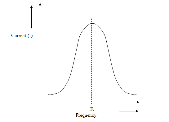
Fig. 7.1 Resonance curve
The resonance curve has a shape of dome because magnitude of circuit current decreases rapidly as the frequency varies from the resonant frequency.
Sharpness of resonance: The narrowness of the frequency band around the resonance at which the response of an electric circuit exceeds an arbitrary fraction of its maximum response, often 70.7%.
Selectivity: The selectivity of the circuit is a measure of its ability to reject any frequencies either side of these points. A more selective circuit will have a narrower bandwidth whereas a less selective circuit will have a wider bandwidth. The selectivity of a series resonance circuit can be controlled by adjusting the value of the resistance only, keeping all the other components the same.
7.2.2 Q-factor
Q-factor gives the degree of current change with frequency above and below resonance. A R-L-C circuit is used to discriminate between frequencies. In other words Q-factor or quality factor is the ability to discriminate different frequencies.
![]()

Resonant circuits are used to respond selectively to signals of a given frequency while discriminating against signals of different frequencies. If the response of the circuit is more narrowly peaked around the chosen frequency, we say that the circuit has higher "selectivity". A "quality factor" Q, as described below, is a measure of that selectivity, and we speak of a circuit having a "high Q" if it is more narrowly selective.
An example of the application of resonant circuits is the selection of AM radio stations by the radio receiver. The selectivity of the tuning must be high enough to discriminate
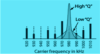
Fig. 7.2 Q-factor
Q-factor depends entirely upon design of coil (i.e. R-L part of the R-L-C circuit) because resistance arises in this rather than in a capacitor.
7.3 Concept of Resonance in Parallel Circuit
"Parallel resonant circuit" comprises of a capacitor (C) connected in parallel with an inductive coil having a resistance R and inductance L which in combination is connected across an a.c. supply.
Consider a parallel resonant circuit with following elements:
a. L = Coil Inductance
b. R = Coil resistance. (usually very small and is neglected compared to other impedances)
c. C = Capacitance (assumed to be loss less)
d. Variable frequency a.c. source
Here a coil (L) and capacitor (C) are connected in parallel with an AC power supply. Let R be the internal resistance of the coil. When XL equals XC, the reactive branch currents are equal and opposite. Hence they cancel out each other to give minimum current in the main line. Since total current is minimum, in this state the total impedance is maximum. Resonant frequency given by:
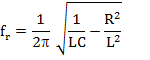
If R is negligible then,
![]()
Note that any reactive branch current is not minimum at resonance, but each is given separately by dividing source voltage (V) by reactance (Z). Hence I=V/Z, as per Ohm's law.
· At fr, line current is minimum. Total impedance is maximum. In this state a circuit is called a rejector circuit.
· Below fr, circuit is inductive.
· Above fr,circuit is capacitive.
Like series resonant circuit, the resonance in a parallel resonant circuit will occur, when the power factor of the entire circuit becomes unity.
7.4 Comparison of Series and Parallel Resonant Circuits
Table 7.2 Comparison of series and parallel resonant circuits
|
|
|
Series Circuit |
Parallel Circuit |
|
1. |
Connection |
R-L-C series connection across a.c. supply |
R-L and C connected in parallel across a.c. supply. |
|
2. |
Circuit current at resonance |
Maximum |
Minimum |
|
3. |
Impedance at resonance |
Minimum (Z = R) |
Maximum (Z=L/CR) |
|
4. |
Magnification |
Voltage |
Current |
|
5. |
Power factor at resonance |
Unity |
Unity |
7.5 Application of R-L-C Circuit
1. They are used in many different types of oscillator circuit.
2. Variable tuned circuits: A very frequent use of these circuits is in the tuning circuits of analogue radios. Adjustable tuning is commonly achieved with a parallel plate variable capacitor which allows the value of C to be changed and tune to stations on different frequencies.
3. Signal Filters: Can be used to filter a signal by blocking certain frequencies and passing others.
4. Voltage multiplier
5. Pulse discharge circuits
7.6 Applications of Resonance Effect
1. Most common application is tuning. For example, when we tune a radio to a particular station, the LC circuits are set at resonance for that particular carrier frequency.
2. A series resonant circuit provides voltage magnification.
3. A parallel resonant circuit provides current magnification.
4. A parallel resonant circuit can be used as load impedance in output circuits of RF amplifiers. Due to high impedance, the gain of amplifier is maximum at resonant frequency.
5. Both parallel and series resonant circuits are used in induction heating.
Numericals
1. Calculate the resonant frequency for a R-L-C series circuit having L = 25 mH and C = 30µF.
![]()
![]() = 184 Hz
= 184 Hz
2. Calculate the resonant frequency for a R-L-C series circuit having L = 30 mH and C = 50 µF. Also calculate band width of the circuit if Q-factor is 50.
![]()
![]() = 130 Hz
= 130 Hz
Q = fr/BW
BW = fr/Q = 130/50 = 2.6 Hz