Module 2. A.C. series and parallel circuits
Lesson 8
POLYPHASE ALTERNATING CURRENT CIRCUITS
8.1 Introduction
In domestic supply line comprise mostly of single phase electricity. Home appliances like T.V., refrigerator, washing machines are designed to be operated by single phase alternating current. But for individual use where heavy duty machines have to be operated single phase current is not sufficient. There polyphase a.c. is needed to run in plant and machinery. Polyphase means a.c. will have two or more than two phases. Generally 3 phase (also denoted as 3ϕ) alternating systems are employed in the industry.
8.2 Polyphase Systems
8.2.1 Single phase
A generator with one armature winding involves a single phase alternating current. The instantaneous value of emf induced in the eq. is given as
ea1a2 = Em. Sin (ωt)
8.2.2 Two phase
A two phase alternative (generator) has two windings and the angle between them is 90o. As a result the phase difference between the two alternating voltages is 90o. And since the number of turns in the two windings are same the magnitude of e.m.f generated and frequency is same in both the windings. The instantaneous value of e.m.f induced in the two coils is given as:
ea1a2 = Em Sin ωt
ea1a2 = Em sin (ωt – 90o) or Em sin (ωt – π/2)
8.2.3 Three phase
A three phase system has three windings in the alternator. The windings are placed such that the angle between them is 120o (Fig. 8.1). Since the windings are identical the magnitude and frequency of alternating voltage is same for all the three windings. The instantaneous value of e.m.f. indicates in the three windings are given as:
ea1a2 = Em Sin ωt
eb1b2 = Em Sin (ωt – 120o) or Em Sin (ωt- 2p/3)
ec1c2 = Em Sin (ωt-240o) or Em Sin (ωt- 4p/3)

Fig. 8.1 Wave form of three phase system
8.3 Comparison of Three phase and Single Phase System
Table 8.1 Comparison of three phase and single phase system
|
|
3ϕ System |
Singleϕ System |
|
|
1. |
Transmission line
distribution and voltage regulation |
Better |
Poor |
|
2. |
Transmission line
conductor (wire) requirement for distribution |
Less (Only 75% of
what is received for single ϕ system) |
More |
|
3. |
Vibration due to
electrical loads (e.g. motors) |
Low |
High |
|
4. |
Electrical Machine (e.g.
motors, generators, transformers etc.) |
|
|
|
|
a.
Size |
Small |
Bulky |
|
|
b.
Construction |
Simple |
Complex |
|
|
c.
Performance |
Better |
Average |
|
|
d.
Cost |
Cheaper |
Expensive than 3ϕ |
|
|
e.
Efficiency |
High |
Low |
|
|
f.
Power factor of motor |
High (0.7 to 0.8) |
Low (0.5) |
|
|
g.
Starting of motors |
Self Starting |
Not self starting |
8.4 Power Sequence
In a poly phase system, the order in which the phases attain the maximum voltages (emf) is called as phase sequence. Maximum voltage or emf is attained in the phase sequence of a1a2®b1b2®c1c2. If the direction notation is reversed then the new phase sequence will be c1c2®b1b2® a1a2.
Note: In 3ϕ induction motor, the direction of rotation depends on phase sequence of the applied voltage. Direction of the rotation can be reversed by interchanging any two lines.
8.5 Numbering of Phases
The phases can be numbered in three methods according to the phase sequence of system.
a) By numbering 1, 2, 3
b) By alphabetically a, b, c
c) Colour code (R, Y, B) where R = Red, Y = Yellow, B = Blue
+ ve phase sequence = RYB
- ve phase sequence = RBY or BYR or YRB
8.6 Double Subscript Notation
Voltages in the 3ϕ systems can be denoted using two subscripts. The two subscripts are the two points between which the voltage or current is being considered. The sequence of subscript gives the direction in which voltage is denoting or current is flowing.
Example
VRY – It denotes the voltage between points RY and the positive direction of voltage from R to Y.
IRY – It denotes the current flowing from point R towards point Y.
8.7 Inter Connection of Three Phases
Let us first understand the construction of a 3ϕ alternator. It comprises of two main parts stator and rotor. Stator is the stationary part of the alternator. Stator have three windings. Winding has two terminal marked on start and finish. A total of six wires will be required to connect the alternator (two for each winding). The type of connection is very expensive and complex. Instead these six terminals are connected by any of the two methods.
1. Star or wye (Y) connection (Fig 8.2)
2. Mesh or delta (∆) connection (Fig 8.3)
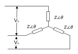
8.7.1 Star or wye (Y) connection
Here the similar ends (either start or finish) are connected at a point. This point is known as star or neutral point (N). Line conductors are commonly called by colour code R (Red), Y (Yellow) and B (Blue) and are shown in Fig 8.1. as RR¢, YY¢ and BB¢. They can also be sequenced as a,b,c or 123.
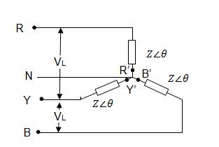
Fig. 8.2 Star or Y connection
· Neutral connection: - The wire joining neutral point N is known as neutral connection.
· Phase voltage: - As the name suggests it is the voltage measured between any line and Neutral (N) is known as phase voltage (Vph). Since the coils are held at 1200.
· Line voltage: - It is the voltage existing between any two phase winding or phases (Vph).
Line voltage = √3 × phase voltage
· Phase current: - Current flowing through any winding or phase is known as phase current.
· Line current: - Current flowing through any line is known as line current.
For star connection line current = phase current
Note: Star connection is also known as 3 phase 4 wire system. In case neutral wire in not there, it may be called as 3ϕ 3 wire system.
Power
Output power per phase = Vph Iph Cosϕ
Total output power = 3 Vph Iph Cosϕ
since VL = √3 Vph
Iph = IL
∴ Total output power = √3 VL IL Cosϕ
Where
Vph = Phase voltage
Iph = Phase current
VL = Line voltage
IL = Line current
Cosϕ = Power factor
P = Power
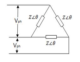
8.7.2 Delta or mesh connection
In delta or Mesh connection the three windings are connected in series pattern (Fig. 8.3). The connections are made in the following way:
Start of winding a1 → Finish terminal of winding c2
Start of winding b1 → Finish terminal of winding a2
Start of winding c1 → Finish terminal of winding b2
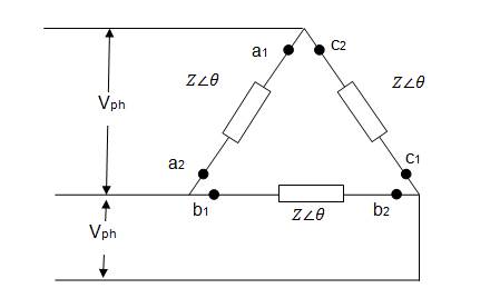
Fig. 8.3 Delta or mesh connection
· Phase voltage – The voltage measured in windings or phases is known as phase voltage.
· In Mesh or Delta ∆ connection
Line voltage (VL) = Phase voltage (Vph)
· Phase current – Is the current flowing through any winding or phase.
· Line current – Is the current flowing through any line. For ∆ connection:
Line current (IL) = √3 Iph
Where
Iph = phase current
Power
Output power per phase = Vph Iph Cosϕ
For balanced load,
Total power P = 3 Vph Iph Cosϕ
Since Vph = VL and IL = √3 Iph
P = √3 VL IL Cosϕ
True power P = √3 VL IL Cosϕ units Watts (W) or kilowatts (kW)
Apparent power Papp = √3 VL I L units VA or kVA
Reactive power Prec = √3 VL IL Sinϕ units VAR or kVAR
8.8 Differences Between Star(Y) and Delta(∆) Connection
Table 8.2 Differences between star(Y) and delta (∆) connection
|
Star (Y) |
Delta (∆) |
|
1. Structure
|
1. Structure
|
|
2. Winding are connected by joining similar ends |
2. Windings are connected by joining dissimilar ends |
|
3. 3ϕ 4 wire system is possible |
3. Only 3ϕ 3 wire system possible |
|
4. Provision for neutral |
4. No neutral wire |
|
5. Line voltage VL = √3 Vph Where, Vph = Phase voltage |
5. Line voltage VL = Phase voltage Vph |
|
6. Line current IL = Phase current Iph |
6. Line current IL = √3 Iph Where, Iph = phase current |
|
7. Line voltage are at phase difference of 1200 |
7. Lines current are at phase difference of 1200. |
|
8. Alternators are generally designed as 3 ϕ star system because of following reason i. Less insulation requirement ii. Require less number of turns in the winding |
8. Alternators are not generally connected as Delta system.
|
Numericals
1. Calculate line voltage of Y-system if phase voltage is 340 V.
VL = √3 Vph
VL = √3 X 340
VL = 588.89 V
2. Calculate line current of Δ-system if phase current is 25 A.
IL = √3 Iph
IL = √3 X 25
IL = 43.3 A
3. Calculate total power in a Y-system if line voltage and line current is 440 V and 25 A respectively. Consider power factor as 0.65.
Total output power = √3 VL IL Cosϕ
= √3 X 440 X 25 X 0.65
= 12.38 kW
4. For a star connected system calculate the line voltage and output power if phase voltage = 410 v and line current is 7.5 A. Take power factor as 0.86.
Solution
Given
Vph = 410 v
IL = 7.5 A
Cos
Φ = 0.86
![]()
![]()
= 710.14 v
Total
outer power = ![]()
![]()
= 7933 w
5. For a data connected system calculate the line current and output power if phase voltage is 440 v and phase current is 5A. Take power factor as 0.75. Also calculate the reactive power.
Solution
Vph = 440 v
IL = 5 A
Cos
Φ = 0.76
![]()
![]()
= 8.66 A
Output power p = 3 Vph Iph cosΦ
= ![]()
P = 4950 w
Reactive power prec = ![]()
prec = 3 Vph Iph Sin Φ
Cos Φ = 0.75
Φ = 41.40°
Sin Φ = 0.661
Prec = ![]()
= 4362.6 W