Module 3. Transformers
Lesson 11
TRANSFORMER THEORY-II
11.1 Three-Phase Transformer
In commercial power network and distribution system three-phase transformers are required to transform the three-phase voltage. Step up and step down of voltage is known as transformation. In a three-phase system, the voltage is lowered or raised either by a bank of three single-phase transformers or by one 3-phase transformer. The windings of either core-type or shell-type three-phase transformers may be connected in either wye or delta. Four possible combinations of connections for the three-phase, two-winding transformers are Y-Y, Δ-Δ, Y-Δ or Δ-Y. A three-phase transformer, compared to a bank of three single-phase transformers, for a given rating will weigh less, cost less, require less floor space, and have somewhat higher efficiency.
11.2 Classification of Transformer
Transformers can be classified according to:
11.2.1 Core construction: core type, shell type.
11.2.2 Winding arrangement: Helical, disc, cross-over, sandwich.
11.2.3 Cooling system: Dry type, oil cooled.
11.2.4 Power capacity: from a fraction of a volt-ampere (VA) to over a thousand MVA
11.2.5 Duty of a transformer: continuous, short-time, intermittent, periodic, varying
11.2.6 Voltage class: from a few volts to hundreds of kilovolts
11.2.7 Number of phases: Single phase/polyphase
11.2.8 Step up/step down
11.2.9 Application: such as power supply, impedance matching, output voltage and current stabilizer or circuit isolation
11.2.10 According to method of mounting: Pole, platform, subway
11.2.11 According to purpose: Constant-voltage, variable-voltage, current, constant-current
11.2.12 According to service
Fig. 11.1 Power distribution system
a. Power transformer: Used for power generation and transmission at power stations. These are of step up type.
b. Distribution transformers: These are step down type transformer (16 to 2500 kVA) used to distribute power to domestic or industrial units. A distribution transformer is a transformer that provides the final voltage transformation in the electric power distribution system, stepping down the voltage used in the distribution lines to the level used by the customer. If mounted on a utility pole, they are called pole-mount transformers (or colloquially a pole pig). If the distribution lines are located at ground level or underground, distribution transformers are mounted on concrete pads and locked in steel cases, thus known as pad-mount transformers. Because of weight restrictions transformers for pole mounting are only built for primary voltages under 30 kV. Distribution transformers are classified into different categories based on certain factors such as:
Type of insulation: Liquid-immersed distribution transformers or dry-type distribution transformers
Number of Phases: Single-phase distribution transformers or three-phase distribution transformers
Voltage class (for dry-type): Low voltage distribution transformers or medium voltage distribution transformers
Basic impulse insulation level (BIL): for medium-voltage, dry-type.
11.3 Efficiency of Transformer
The efficiency of a transformer is expressed as:
Efficiency = (output/Input) x 100%
= (input - 1osses)/input x 100%
= [l - (losses/input)] x 100%
Where, input, output and losses are all expressed in units of power.
11.4 Equivalent Circuit of Transformer
A transformer can be depicted in terms of equivalent circuit (Fig. 11.2). But it is not very convenient for use due to the presence of the ideal transformer of turns ratio T1 : T2. If the turns ratio could be made unity by some transformation the circuit becomes very simple to use. This is done here by replacing the secondary by a `hypothetical' secondary having T1 turns which is `equivalent ' to the physical secondary. The equivalence implies that the ampere turns, active and reactive power associated with both the circuits must be the same. As the ideal transformer in this case has a turns ratio of unity the potentials on either side are the same and hence they may be conductively connected dispensing away with the ideal transformer. This particular equivalent circuit is as seen from the primary side (Fig. 11.3). It is also possible to refer all the primary parameters to secondary by making the hypothetical equivalent primary winding on the input side having the number of turns to be T2 (Fig. 11.4).
Fig. 11.2 Equivalent circuit of transformer
Fig. 11.3 Equivalent circuit of transformer referred to primary side
Fig. 11.4 Equivalent circuit of transformer referred to secondary side
11.5 Auto transformer
An autotransformer (sometimes called “auto step down transformer”) is an electrical transformer with only one winding. The ‘auto’ prefix refers to the single coil acting on itself rather than any automatic mechanism. In an autotransformer portions of the same winding act as both the primary and secondary. The winding has at least three taps where electrical connections are made. An autotransformer can be smaller, lighter and cheaper than a standard dual-winding transformer however the autotransformer does not provide electrical isolation. The primary voltage is applied across two of the terminals, and the secondary voltage taken from two terminals, having one terminal in common with the primary voltage (Fig. 11.5). The primary and secondary circuits therefore have a number of windings/turns in common. Since the volts-per-turn is the same in both windings, each develops a voltage in proportion to its number of turns. In an autotransformer, part of the current flows directly from the input to the output, and only part is transferred inductively, allowing a smaller, lighter, cheaper core to be used.
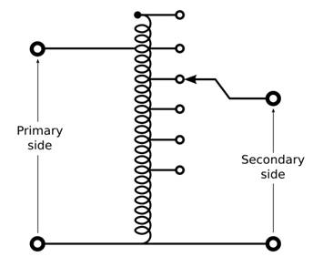
Fig. 11.5 Single-phase tapped autotransformer with output voltage range of 40%–115% of input
11.5.1 Operation
An autotransformer has a single winding with two end terminals, and one or more terminals at intermediate tap points. One end of the winding is usually connected in common to both the voltage source and the electrical load. The other end of the source and load are connected to taps along the winding. Different taps on the winding correspond to different voltages, measured from the common end. In a step-down transformer the source is usually connected across the entire winding while the load is connected by a tap across only a portion of the winding. In a step-up transformer, conversely, the load is attached across the full winding while the source is connected to a tap across a portion of the winding.
As in a two-winding transformer, the ratio of secondary to primary voltages is equal to the ratio of the number of turns of the winding they connect to. For example, connecting the load between the middle and bottom of the autotransformer will reduce the voltage by 50%.
11.5.2 Limitations
An autotransformer does not provide electrical isolation between its windings as in an ordinary transformer. A failure of the insulation of the windings of an autotransformer can result in full input voltage applied to the output. These are important safety considerations when deciding to use an autotransformer in a given application.
Because it requires fewer windings and a smaller core, an autotransformer for power applications is typically lighter and less costly than a two-winding transformer, up to a voltage ratio of about 3:1; beyond that range, a two-winding transformer is usually more economical. In three phase power transmission applications, autotransformers have the limitations of not suppressing harmonic currents. In practice, losses in standard transformers and autotransformers are not perfectly reversible; one designed for stepping down a voltage will deliver slightly less voltage than required if used to step up. The difference is usually slight enough to allow reversal where the actual voltage level is not critical.
11.5.3 Variable Transformer
A variable autotransformer is made by exposing part of the winding coils and making the secondary connection through a sliding brush, giving a variable turns ratio. By exposing part of the winding coils and making the secondary connection through a sliding brush, an almost continuously variable turns ratio can be obtained, allowing for very smooth control of voltage. Applicable only for relatively low voltage designs, this device is known as a variable AC transformer, or commonly by the trade name of VARIAC.
As with two-winding transformers, autotransformers may be equipped with many taps and automatic switchgear to allow them to act as automatic voltage regulators, to maintain a steady voltage during a wide range of load conditions. They can also be used to simulate low line conditions for testing.