Module 3. Transformers
Lesson 12
VECTOR DIAGRAM AND LOSSES
12.1 Vector Diagram without Load
Let us consider a transformer without load (Fig. 12.1). Primary winding of the transformer is supplied with sinusoidal alternating voltage V1 and current Im flows through it. This current Im lags behind the applied voltage V1 by 90o as primary coils exhibit pure inductance. Magnetic flux ∅ produced in the core is in phase with Im. Emfs E1 and E2 are induced in the primary and secondary winding of the transformer respectively. Phasor diagram of E1 and E2 are shown in Fig. 12.2 and 12.3. When transformer is on no load, a small current I0 (2-10% of Im) known as exciting current is taken up by the primary winding. This current I0 lags behind the voltage vector V1 by an angle ∅o.
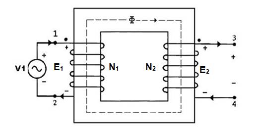
Fig. 12.1 Transformer under no load condition
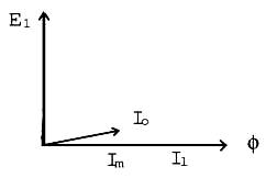
Fig. 12.2 Phasor diagram for the primary side of transformer
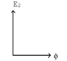
12.3 Phasor diagram for the secondary side of transformer
12.2 Vector Diagram with Load
Consider a transformer with load (Fig. 12.4). I2 current flows through the secondary winding and magnitude of I2 depends on the terminal V2 voltage and impedance of the load. The phase angle of secondary current I2 depends upon the nature of load i.e. whether the load is resistive, inductive or capacitive. I0 is the no load current. The secondary current I2 is in phase, lags behind and leads the secondary terminal voltage for resistive, inductive and capacitive load respectively.
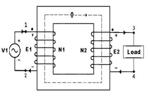
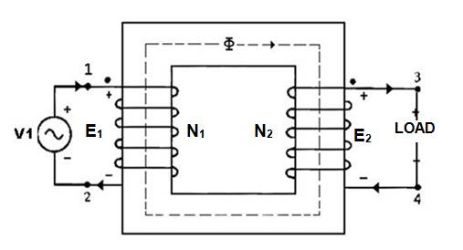
Fig. 12.4 Transformer with load
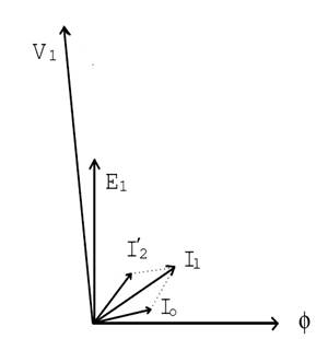
Fig. 12.5. Phasor diagram for the primary side of transformer
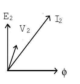
Fig. 12.6 Phasor diagram for the secondary side of transformer
12.3 Losses in Transformer
There are certain losses in a transformer which are as follows:
12.3.1 Iron losses
Iron core of the transformer is subjected to alternating flux which causes eddy current and hysteresis loss in it. The sum of these two losses is known as iron or core loss. The iron losses depend upon the construction material of core, frequency of a.c. supply, maximum flux density in the core, volume of the core etc. The value of iron looses is very small compared to copper loss.
a Eddy current loss
Due to the alternating magnetic flux current is induced in the core of the transformer which is known as eddy current. If transformer core was made of solid material (Fig. 12.7) the magnitude of eddy current and thus losses would be very high. Therefore core of the transformer is made of laminated sheets (Fig.12.8).
Eddy current loss ![]()
Where A is constant
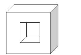
Fig. 12.7 Solid transformer core (high eddy current loss)
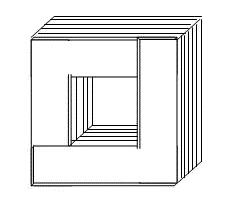
Fig. 12.8 Laminated transformer core (low eddy current loss)
b. Hysteresis losses
When the steel core of the transformer is magnetized and demagnetized by the alternating flux heat is generated. This causes hysteresis losses.
Hysteresis loss ![]()
![]()
Where A and B are constants
12.3.2 Copper loss due to winding resistances
The primary and secondary windings are made of copper wires which has certain resistance. If resistance of primary and secondary windings are R1 and R2 respectively, Copper loss will be given as:
Total copper loss = I12R1 + I22R2
Where,
I1 and I2 are current flowing through primary and secondary winding respectively.
12.3.3 Leakage flux losses
Magnetic flux is produced in both the windings of the transformer (primary and secondary). The flux ∅ which links both the winding is the useful flux and is called mutual flux. The fluxes which do not link with the other winding are known as leakage flux.
12.3.4 Stray losses
Losses caused due to eddy current in channels, bolts etc.
12.4 Transformer Test
The performance of a transformer can be determined by:
1. Open-circuit or no-load test.
2. Short-circuit or impedance test.
12.4.1 Open-circuit or no-load test
Open-circuit or no-load test is done to determine:
i. No-load loss or core loss.
ii. No-load current I0 by which equivalent resistance R0 and leakage resistance X0 can be calculated
For no load test, one of the transformer winding is kept open and the other is connected to voltage source at rated frequency (Fig. 12.9). No-load current (I0) is measured using ammeter. No-load power (P0) is measured by wattmeter.
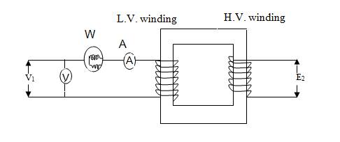
Fig. 12.9 Diagram for open-circuit test
Primary no-load current I0 in Low Voltage (LV) winding is very small 2 to 10% of rated load current due to which the copper loss (Io2R1) is negligibly. As the secondary side is open, no current flows in secondary so copper loss or winding loss is zero. Thus the power measured by wattmeter is due to core loss.
No load input power = P0 = V1 I0 cosϕ0
Where,
P0 = No load input power = Core loss or iron loss
cosϕ0
=no-load power factor = ![]() = P0/V1I0
= P0/V1I0
I0 = no-load current
V1 = primary voltage
No-load current I0 has two components and is given as:
![]()
a. No-load current wattful component (iron loss component),
![]()
b. No-load current magnetizing component (produces magnetic flux in core),
![]()
No-load resistance is given by
![]()
No-load reactance is given by,
![]()
No-load current I0 drawn by the transformer is the exciting current. Admittance Y0 of the transformer is given by:
![]()
The exciting core loss conductance ![]() ,
,
![]()
The exciting or magnetising susceptance
![]() ,
,
![]()
12.4.2 Short-circuit or
impedance test
This test is done to measure:
(i) Full-load loss or copper
loss (in the winding)
(ii) Equivalent resistance and reactance referred to
measuring side.
In this
test, the secondary (low-voltage winding) is short-circuited by a thick wire
(Fig. 12.10) and low voltage i.e. 5 to 10% of rated primary voltage is applied
to the primary winding.
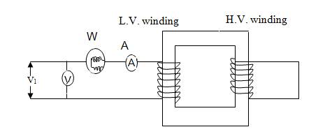
Fig.
12.10 Diagram of short-circuit test
The low input voltage is gradually raised till at
voltage VSC, full-load current I1
flows in the primary. As the
input voltage is small the magnetic flux linking the primary and secondary side
is very small. Thus iron losses can be neglected. The wattmeter only measures
the copper loss. Fig. 12.11 shows the equivalent circuit of a
transformer on short circuit as referred to primary side. As no-load current I0
is small it is neglected in the equivalent circuit.
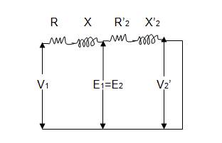
Fig.
12.11a Equivalent circuit of transformer under short circuit condition.
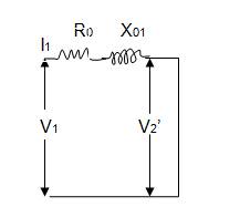
Fig.
12.11b Equivalent circuit of transformer under short circuit condition.
Full load copper loss = W
(wattmeter reading) ![]()
VSC= Applied
voltage applied so that full-load current I1 flows
in the primary winding
I1 = reading of
the ammeter on the primary side
Total impedance as referred
to primary side ![]()
Total resistance as referred
to primary side ![]()
Total reactance as referred
to primary side ![]()